
 首页
首页 登录
登录 注册
注册


-
真空管道交通系统是一种未来可实现的交通方式,各国对真空管道交通技术加大了研究力度,开展了多项合作[1-8]。真空管道交通系统就是为列车运行创造特定真空度的管道运行环境来降低列车在运行过程中所受到的运行阻力,低真空的管道运行环境使得列车的运行速度甚至可以达到亚音速或超音速[9]。列车在真空管道内的高速运行就像活塞在气缸中运行一样,车头前方的空气不断压缩,而车尾后方的空气不断膨胀,导致车头和车尾出现较大的压差,列车运行受到较大的压差阻力[10]。当列车运行速度提高到极限速度时,由于车头前方的空气无法有效的进行转移,甚至会出现Kantrowitz极限现象,运行阻力大大增加[11]。
横通管道会影响列车的气动特性,并且在施工时需要考虑力学机理以及产生的振动问题等[12-15]。在真空管道交通系统中增加横通管道可以很好地转移车头前方受压缩的空气,车头的高压空气和车尾的低压空气可以通过横通管道不断流动。横空管道使得车头的高压气体和车尾的低压气体充分混合,列车运行所受到的气动阻力也随之大大降低[16]。下表1是以管道压力100 Pa,管道阻塞比0.6,运行速度分别为200 m/s、240 m/s、280 m/s为例,对单一真空管道和带有横通管道(横通管道间隔为两倍车长154 m,管道长度为5 m,管道横截面积为2.54 m2)的系统进行数值模拟,得到真空管道列车运行首尾压差以及在运行时受到的阻力。如表1所示,带有横通管道的真空管道交通系统与单一真空管道交通系统相比,列车首尾压差及列车运行阻力都有明显的下降,当运行速度为200 m/s、240 m/s、280 m/s时减阻率分别为42.1%、42.4%、41.4%。横通管道的存在有效降低了列车运行所受到的气动阻力,提高了真空管道列车的运行效率,降低了其运营成本,且横通管道的结构简单,优化了流阻特性,减阻节能效果明显[16]。
-
当Re>
4000 时,真空管道交通系统内的气体流动情况为湍流状态。雷诺数Re表达式为[17]ρ为管道内空气密度;v为列车运行速度;D为管道的特征长度;μ为空气动力粘度。
本文将带横通管道的真空管道交通系统的管道压力分别取100、500、
1000 Pa,空气密度分别为ρ=0.001161287 、ρ=0.006967721 、ρ=0.01277415 kg/m3;列车运行速度为亚音速,分别取200、240、280 m/s,即马赫数分别为0.6、0.7、0.8;本文管道阻塞比为0.6,管道特征长度为4.68 m。当管道压力为100 Pa时,空气动力粘度为μ=1.7894 ×10⁻⁵ kg/(m×s)。将相关数据代入式(1)可得最小Re为可以得出带横通管道的真空管道交通系统内空气流动属于湍流流动,真空管道中空气为低管内压力、高流速的状态,所以本文在Fluent数值模拟中选用Realizable
$ k - \varepsilon $ 模型[18]。本文带横通管道的真空管道交通系统内的空气采用克努森数Kn来判定其是否连续,当Kn<0.01,可以认为真空管道内空气是连续的,可以使用连续介质模型进行数值模拟,Kn表达式[19]
λ为分子平均自由程;L为特征长度。
当管内压力为100 Pa、管内温度为288 K时,管道内的分子平均自由程最大,即λmax=
7.3073 ×10⁻⁵,特征长度以列车与管道壁面的最小间隙尺寸为准[20],最小间隙为0.65 m。经过计算得到最大Kn为 -
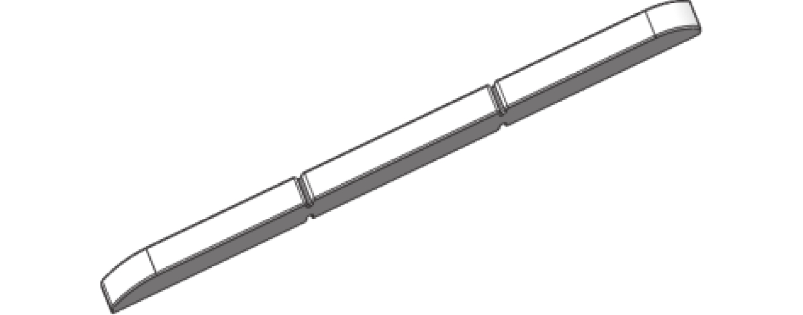
本文列车模型所选用的尺寸参考中国CRH列车的几何尺寸,采用头车、中车、尾车三节编组,忽略受电弓、转向架等附属机构,列车的基本外形尺寸参数如表2所示,列车物理模型如图1所示。本文管道阻塞比为0.6,列车最大横截面积为11.7 m2,带横通管道的真空管道交通系统管道的左视图和俯视图如图2(a)和(b)所示。管道阻塞比为0.6,则R=2.34 m,L1为横通管道间隔,L2为横通管道长度,r为横通管道横截面直径。
本文主要探讨横通管道长度、横通管道间隔、横通管道横截面积对真空管道列车气动阻力的影响。真空管道的长度为400 m,车头与管道入口的距离为100 m,与管道出口的距离为300 m;列车底面与管道底面的距离为100 mm,即列车的悬浮高度为100 mm[23]。图3为横通管道长10 m,横通管道间隔为两倍车长154 m,横通管道横截面积为2.54 m2的真空管道交通系统。
-
本文使用SolidWorks建立带横通管道的真空管道交通系统,根据横通管道长度、间隔、横截面积参数的不同建立不同的物理模型,在Fluent ICEM中使用四面体网格对模型进行网格划分。列车在管道中的高速运动会导致列车表面出现了较大的压力波动,需对列车及其周围流场进行局部网格加密,使得模拟结果更加可靠。以横通管道长5 m、间隔154 m、横截面积2.54 m2,阻塞比为0.6的真空管道交通系统模型为例,网格节点数为19.77万,网格单元总数为93.4万。通过Fluent ICEM进行网格质量检查,网格质量达到了0.3以上,判定网格质量良好,符合最终模拟要求。图4、图5分别是带横通管道真空管道交通系统模型网格和列车模型网格。
-
本文采用四面体网格对模型进行网格划分,以横通管道长度5 m、间隔154 m、横截面积2.54 m2,阻塞比0.6,管内压力100 Pa,运行速度240 m/s为例,采用四种不同尺寸的网格对模型进行数值模拟,从Fluent中获得列车运行时受到的阻力,并比较四种网格尺寸数值模拟得到的结果。
由表3可以得出,当网格数分别为
851411 、1038475 时得到的列车运行阻力分别为4053 、4066 ,列车模拟结果浮动为0.3%,综合考虑计算情况和所花费的时间成本,本文最终将列车车体最大网格尺寸设置为0.3 m,将流体域最大网格尺寸设置为0.8 m。 -
(1)管道入口和出口边界条件
本文在数值模拟时假设列车不动,通过设置管道的入口速度来模拟列车在管道内的匀速运行,管道的入口速度设置为列车的运行速度[24]。本文列车运行速度取200、240、280 m/s。假设管道足够长,并且管道保持恒定的管内压力,所以管道的出口设置为恒压边界,本文管道管内压力取100、500、
1000 Pa。(2)列车壁面和管道壁面边界条件
列车壁面设置为无滑移壁面,即列车壁面
$ u = v = w = 0 $ 。本文数值模拟中假设列车固定不动,真空管道壁面实际上是以列车运行速度向后运动,本文将带横通管道的交通系统管道壁面设置为滑移壁面,壁面的滑移速度和管道入口风速相同[25-26]。本文对定阻塞比的带横通管道的真空管道交通系统进行数值模拟,由于列车运行速度很快,真空管道内为流体湍流程度强、管道内空气可压缩的环境,因此选择压力与速度耦合的SIMPLE算法,为保证模拟结果良好,将每一个控制方程都选择二阶迎风格式[27]。
-
列车在经过横通管道时,列车的运行阻力会呈现周期性变化,在不同横通管道的参数下,为确保列车运行阻力比较的可靠性,故计算同一运行状态下列车的运行阻力,统一计算列车在驶向横通管道的过程中,距离横通管道50 m处时的运行阻力。这时列车车头推动车前气体产生正压,同时在列车车尾产生负压,处于列车经过横通管道时运行阻力周期性变化中最初的阶段。
-
本文在探究列车运行阻力与横通管道长度的变化规律时,固定横通管道间隔为154 m,横通管道横截面积2.54 m2(横截面为圆形),运行工况为管道阻塞比0.6、列车运行速度280 m/s、管内压力
1000 Pa,对横通管道长度分别为2、4、6、8、10、12、14 m的真空管道交通系统进行数值模拟,图6(a)、(b)为横通管道长度分别为2 m、8 m的交通系统压力云图。当固定真空管道交通系统阻塞比(0.6)、管内压力(100 、500、
1000 Pa)和列车运行速度(200、240、280 m/s)时,列车运行时所受到的运行阻力随横通管道长度的变化曲线如图7所示。当列车运行速度分别为200、240、280 m/s时,在固定阻塞比0.6和不同管内压力100、500、
1000 Pa下,列车运行所受到的阻力随横通管道长度的变化规律是一致的。当横通管道长度由2 m增加到6 m时,列车运行阻力随着横通管道长度的增加而降低。当横通管道长度由6 m增加至8 m时,列车所受到的运行阻力不但没有降低,反而略有增加,因为当列车经过横通管道时横通管道的压力是低于系统管内压力的,列车运行所带来的空气在通过横通管道时,由于压力的作用部分空气又回流到列车运行管道中。当横通管道长度不够长时,压力差导致的空气回流作用较弱,当横通管道长度足够长时,压力差导致的空气回流使得列车运行所受到的阻力略有增加。当横通管道的长度由8 m增加至14 m时,列车所受到的运行阻力随着管道长度的增加不断降低,但是运行阻力降低的幅度并不大。在真空管道交通系统阻塞比、管内压力及列车运行速度固定时,横通管道间隔154 m和横通管道横截面积2.54 m2也固定时,考虑到横通管道的建设成本,横通管道长度取6 m是相对合理且经济的。
-
本文探究横通管道间隔对列车运行阻力的影响时,固定横通管道的长度为5 m,横通管道横截面积2.54 m2(横截面为圆形),运行工况为管道阻塞比0.6、列车运行速度280 m/s、管内压力
1000 Pa,对横通管道间隔分别为38.5、77、115.5、154、192.5、231、269.5 m的真空管道交通系统进行数值模拟,管道间隔分别为0.5、1、1.5、2、2.5、3、3.5倍的车身长度,使用倍数关系来表示横通管道间隔,图8为横通管道间隔为1倍、2倍车身长度的交通系统压力云图。当固定真空管道交通系统阻塞比(0.6)、管内压力(100、500、
1000 Pa)和列车运行速度(200、240、280 m/s)时,列车运行时所受到的运行阻力随横通管道间隔长度的变化曲线如图9所示。当列车运行速度分别为200、240、280 m/s时,在固定阻塞比0.6和不同管内压力100、500、
1000 Pa下,列车运行所受到的阻力随横通管道间隔的变化规律是一致的。当横通管道间隔由0.5倍车身长度增加到1倍车身长度时,列车受到的运行阻力不断增加。当横通管道间隔由1.5倍车身长度增加到2倍车身长度时,列车受到的阻力略有下降。当横通管道的间隔由1.5倍车身长度增加到2倍车身长度时,列车因横通管道与另一条运行管道压力差的缘故,造成横通管道中空气的回流作用降低,导致列车在2倍车身长度间隔下运行受到的运行阻力反而降低了。当横通管道间隔由2倍车身长度增加到3.5倍车身长度时,列车运行所受到的气动阻力在一定程度上上下波动,可以得出当横通管道间隔达到2倍车身长度后再增加横通管道的间隔长度对列车运行阻力的影响不大。由下图10(a)和(b)可知,当横通管道的间隔由0.5 L0增加到1.5 L0时,横通管道间隔1.5 L0空气在横通管道的回流效应更加明显。在管道间隔由0.5 L0扩大到1.5 L0时,由于横通管道中空气的回流效应使得列车运行所受到的最大压力在增大,最小压力在减小,列车运行时的首尾压差在增大,受到的压差阻力也在增大。当横通管道间隔较小时,管道内的空气可以更好的流动,车头前高压气体经有横通管道进入另一条运行管道,和车尾处低压空气更好地混合。由下图的(b)和(c)可知,当横通管道的间隔由1.5 L0增加到2 L0时,列车受到压力差导致的空气回流作用降低了,使得列车在运行时受到的运行阻力反而降低了。由图(c)和(d)可知,当横通管道间隔由2 L0增加到3.5 L0时,车头前方的高压气体在经过横通管道流入另一条运行管道时,空气在横通管道内的流动状态基本相同,使得列车运行阻力的变化幅度并不大。
在真空管道交通系统阻塞比、管内压力及列车运行速度固定时,横通管道长度5 m和横通管道横截面积2.54 m2也固定时,考虑到横通管道间隔对列车运行阻力的影响,横通管道间隔取2倍或2.5倍的车身长度是相对合理且经济的。
列车在经过横通管道时,列车车头推动车前气体产生正压,同时在列车车尾产生负压;正压气体从前方的横通管道流入另一侧的并行管道,然后从列车车尾后方的横通管道流回补偿车尾的负压气体;当列车车身经过并覆盖其中的某一横通管道时,该横通管道影响很小。伴随着列车前移,前后方的横通管道与列车头尾的距离不断变化,从而列车所受到的阻力也呈周期性变化。
-
本文探究横通管道的横截面积大小对真空管道列车运行阻力影响时,固定横通管道间隔为154 m,横通管道的长度为5 m,运行工况为管道阻塞比0.6、列车运行速度280 m/s、管内压力
1000 Pa,对横通管道的横截面直径分别为1.0、1.2、1.4、1.6、1.8、2.0 m的真空管管道交通系统进行数值模拟,横通管道的横截面积分别为0.79、1.13、1.54、2.01、2.54、3.14 m2,使用管道直径来表征横截面面积的大小,图11为横通管道横截面直径分别为1.2 m、1.6 m的真空管道交通系统图。当固定真空管道交通系统阻塞比(0.6)、管内压力(100、500、
1000 Pa)和列车运行速度(200、240、280 m/s)时,列车运行时所受到的运行阻力随横通管道横截面积大小的变化曲线如图12所示。当列车运行速度分别为200、240、280 m/s时,在固定阻塞比0.6和不同管内压力100、500、
1000 Pa下,列车运行所受到的阻力随横通管道横截面积大小的变化规律是一致的。随着横通管道横截面积的增加,列车在运行过程中所受到的气动阻力不断减小,列车所受到的气动阻力与横通管道的横截面积大小近似呈线性关系。当列车经过横通管道时,横通管道的横截面越大,通过横通管道流向另一条运行管道的受挤压的空气就越多,列车运行所受到的阻力就会降低。考虑到横通管道横截面积对运行阻力的影响,可以根据实际情况以及建设成本来确定横通管道横截面积的大小。 -
本文利用Realizable
$ k - \varepsilon $ 模型对带有横通管道的真空管道列车在运行时所受到的运行阻力进行数值模拟,探讨了横通管道的长度、间隔以及横截面积大小对列车运行阻力的影响。(1)列车运行阻力随着横通管道长度的增加先降低,后受到横通道与系统压力差作用略微增加,再增加横通管道长度对列车运行阻力影响不大。
(2)列车运行阻力随着横通管道间隔的增加先增加,当横通管道间隔达到2.5倍车身长度时,再增加间隔长度列车所受到的阻力基本保持不变。
(3)横通管道横截面直径由1.0 m增大到2.0 m,即横截面积由0.79 m2增大到3.14 m2
(4)在横截管道横截面积确定的情况下,横通管道长度6 m,横通管道间隔2倍或2.5倍车身长度时,真空管道交通系统运行状态最为理想。时,列车运行所受到的气动阻力不断降低。
横通管道参数对真空管道列车运行阻力的影响
Influence of Cross-Pass Piping Parameters on the Running Resistance of Vacuum Tube Trains
-
摘要: 为了探究横通管道参数(横通管道长度、横通管道间隔、横截面积大小)对真空管道列车运行阻力的影响,本文在Fluent中对不同运行工况的列车进行数值模拟,通过数值模拟得到列车在带横通管道的真空管道交通系统运行时的运行阻力。结果显示,带有横通管道的真空管道列车的运行阻力与单真空管道列车的运行阻力相比大幅降低。随着横通管道长度的增加,列车运行阻力先降低后小幅度上升,管道长度达到8 m时再增加长度对列车运行阻力影响较小;随着横通管道间隔增加,列车运行阻力先增大后降低,间隔达到2.5倍车身长度时,列车受到的运行阻力小幅度波动;随着横通管道横截面直径由1.0 m增大到2.0 m,即横截面积由0.79 m2增大到3.14 m2时,列车运行阻力随着横截面积的增大近似线性下降。Abstract: In order to investigate the influence of cross-pass pipe parameters (cross-pass pipe length, cross-pass pipe spacing, cross-sectional area size) on the running resistance of vacuum tube trains, this paper conducts numerical simulations in Fluent for trains with different running conditions and obtains the running resistance of trains running in vacuum tube transportation systems with cross-pass pipes through numerical simulations. The results show that the running resistance of a vacuum tube train with a cross-pipe is significantly reduced compared to that of a single vacuum tube train. As the length of the cross-pipe increases, the train running resistance first decreases and then rises slightly; when the length of the tube reaches 8 m, increasing the length again has less effect on the train running resistance; as the interval of the cross-pipe increases, the train running resistance first increases and then decreases, when the interval reaches 2.5 times the body length, the train running resistance fluctuates slightly; as the cross-sectional diameter increases from 1.0 m to 2.0 m, the cross-sectional area increases from 0.79 m2 to 3.14 m2, the train running resistance decreases approximately linearly with the increase of the cross-sectional area.
-
Key words:
- Spacing /
- Length /
- Cross-sectional area /
- Running resistance .
-

-
图 2 带横通管道的真空管道图。(a)左视图, (b)俯视图
Figure 2. Diagram of a vacuum pipe with cross-pass piping. (a) Left view, (b) top view
图 3 带横通管道真空管道交通系统图
Figure 3. Diagram of a vacuum tube transportation system with cross-pass pipes
图 4 带横通管道真空管管道交通系统模型网格
Figure 4. Model grid of vacuum tube transportation system with cross-pass pipes
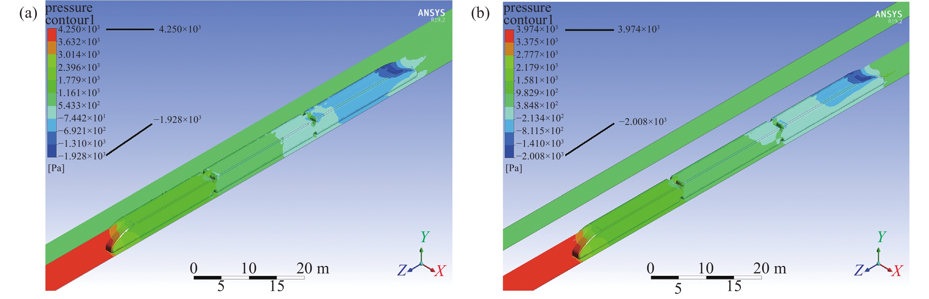
图 6 不同横通管道长度的真空管道交通系统压力图。(a)横通管道长2 m, (b)横通管道长8 m
Figure 6. Pressure diagram for vacuum tube transportation systems with different cross-pass pipe lengths. (a) Cross-pass pipe length 2 m, (b) cross-pass pipe length 8 m
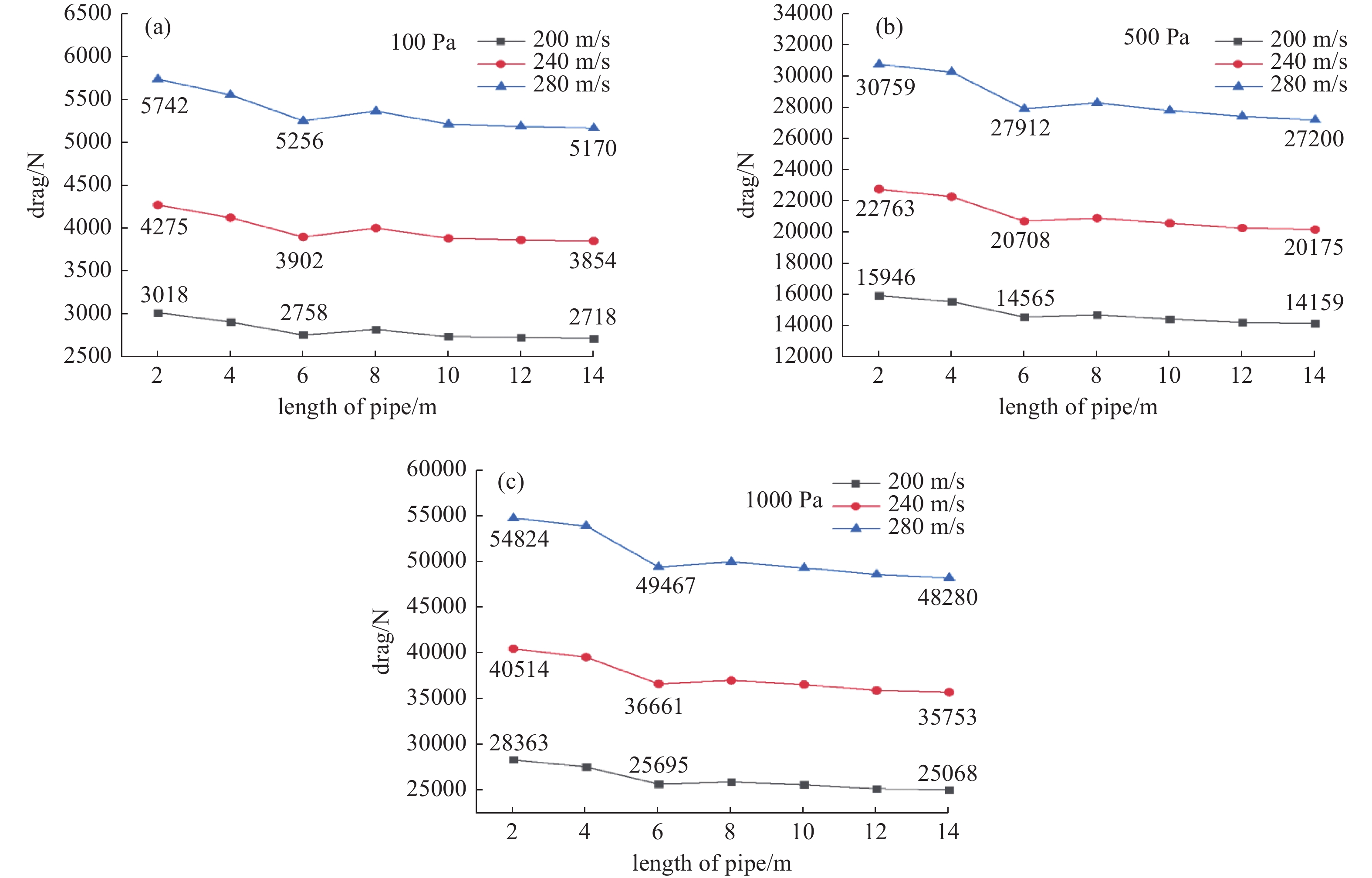
图 7 运行阻力随横通管道长度的变化关系。(a)管内压力100 Pa, (b)管内压力500 Pa, (c)管内压力1000 Pa
Figure 7. Variation of running resistance with the length of cross-pass pipe. (a) Pressure in the pipe 100 Pa, (b) pressure in the pipe 500 Pa, (c) pressure in the pipe 1 000 Pa
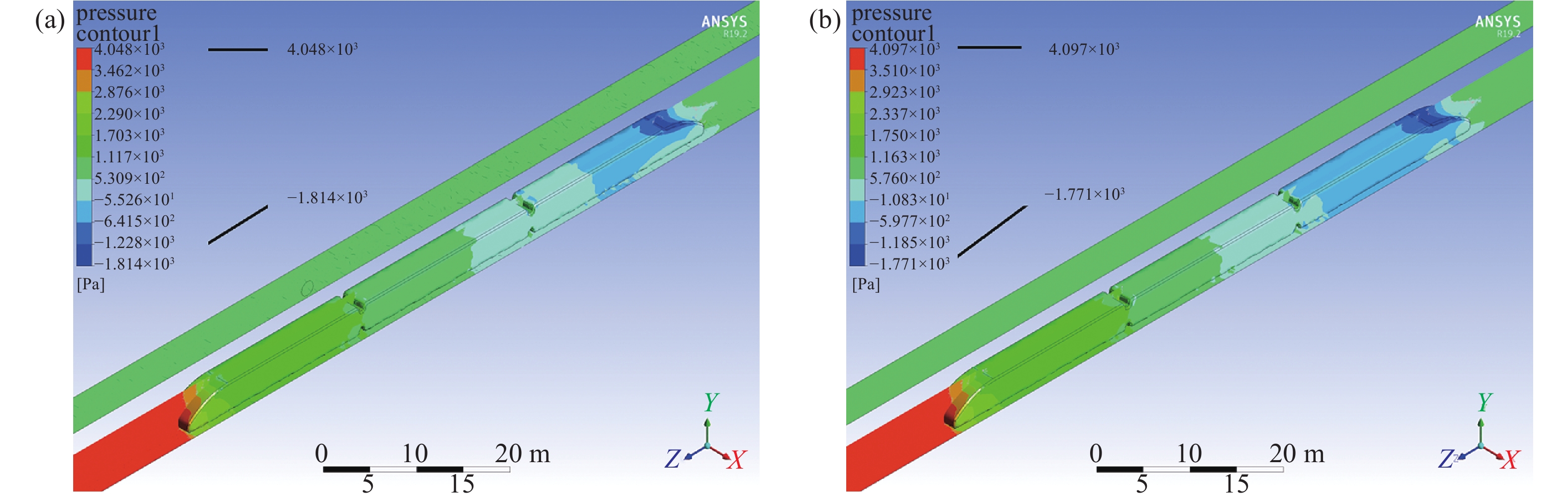
图 8 不同横通管道间隔长度真空管道交通系统图。(a)间隔1 L0,(b)间隔2 L0
Figure 8. Diagram of a vacuum tube transportation system with different cross-pass pipe spacing lengths. (a) Spacing 1 time body length, (b) spacing 2 time body length
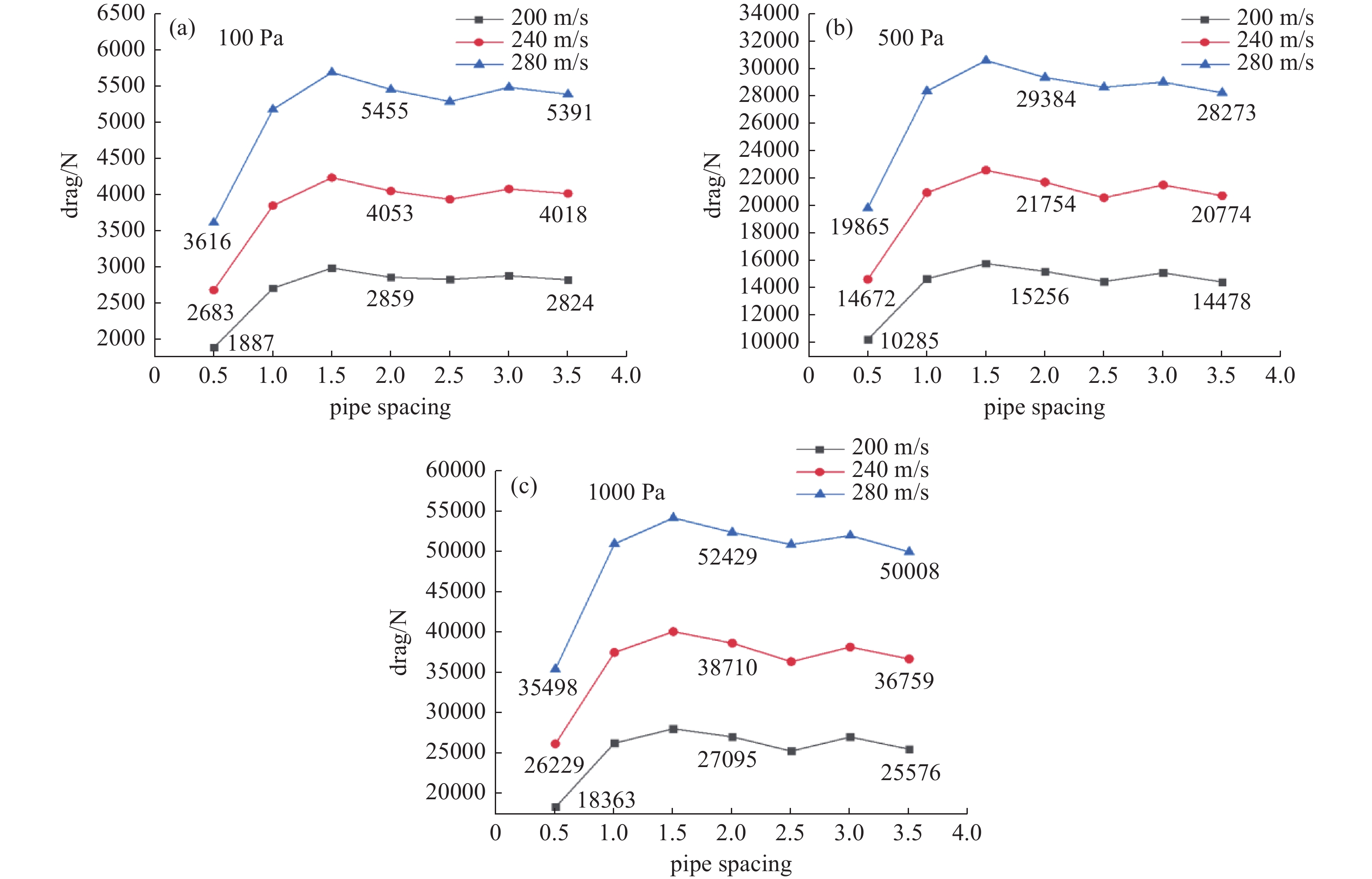
图 9 运行阻力随横通管道间隔的变化关系。(a)管内压力100 Pa, (b)管内压力500 Pa, (c)管内压力1000 Pa
Figure 9. Variation of running resistance with cross-pass pipe spacing. (a) Pressure in the pipe 100 Pa, (b) pressure in the pipe 500 Pa, (c) pressure in the pipe 1000 Pa
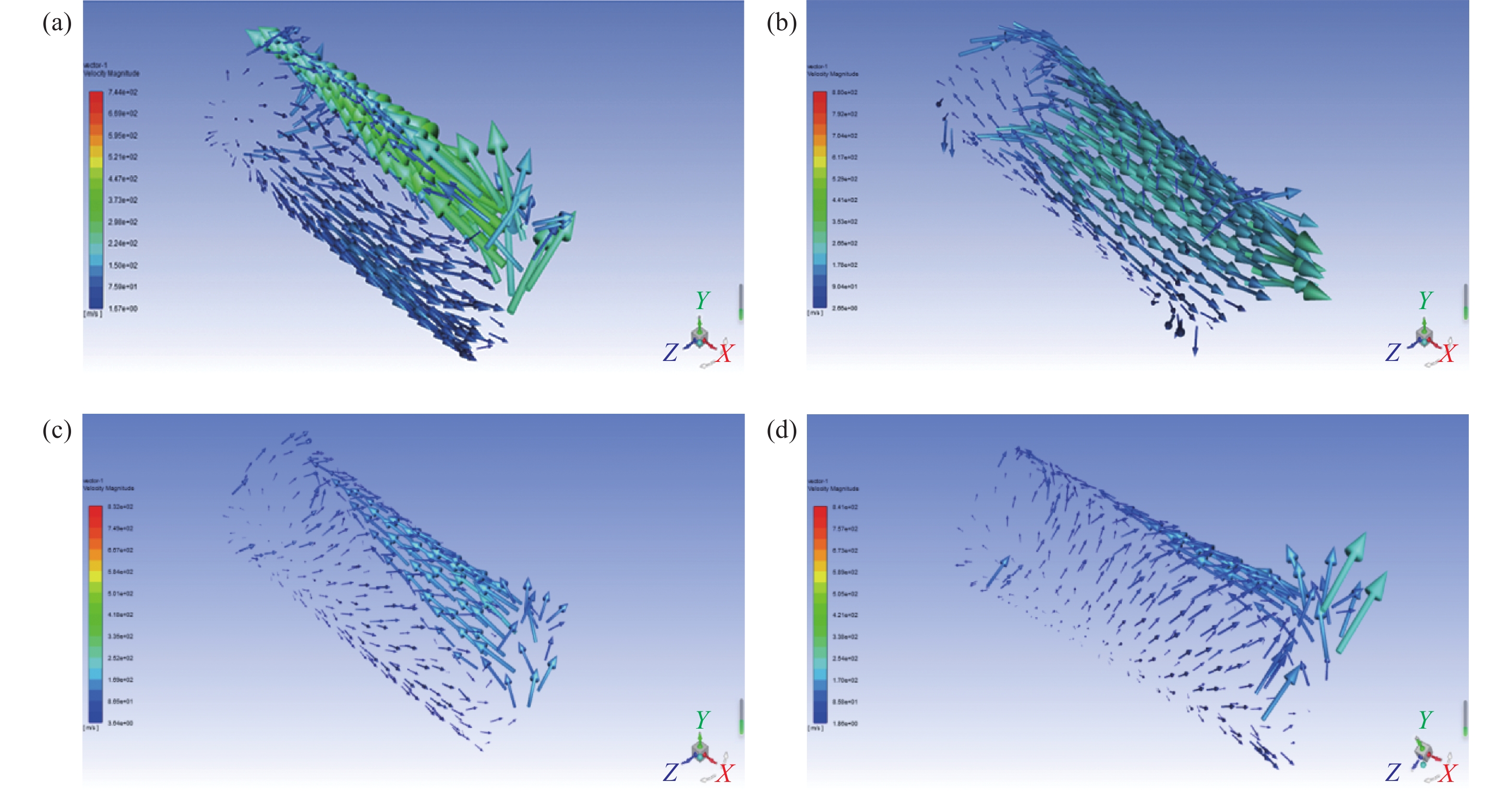
图 10 不同间隔长度下横通管道速度矢量图。(a)间隔 0.5 L0, (b)间隔 1.5 L0, (c)间隔 2.0 L0, (d)间隔 3.5 L0
Figure 10. Cross-pass pipe velocity vector diagrams for different interval lengths. (a) Spacing 0.5 time body length, (b) spacing 1.5 time body length, (c) spacing 2.0 time body length, (d) spacing 3.5 time body length
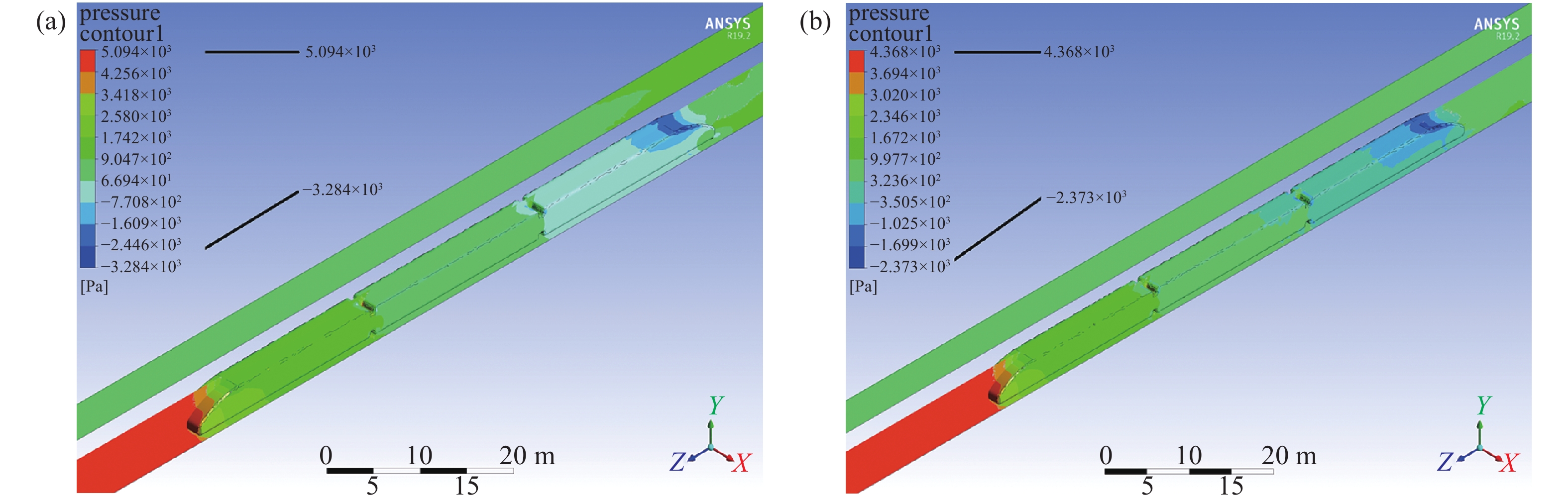
图 11 不同横通管道截面大小的真空管道交通系统图。(a)直径1.2 m, (b)直径1.6 m
Figure 11. Diagram of vacuum tube transportation system with different cross-pass pipe section sizes. (a) Diameter 1.2 m, (b) diameter 1.6 m
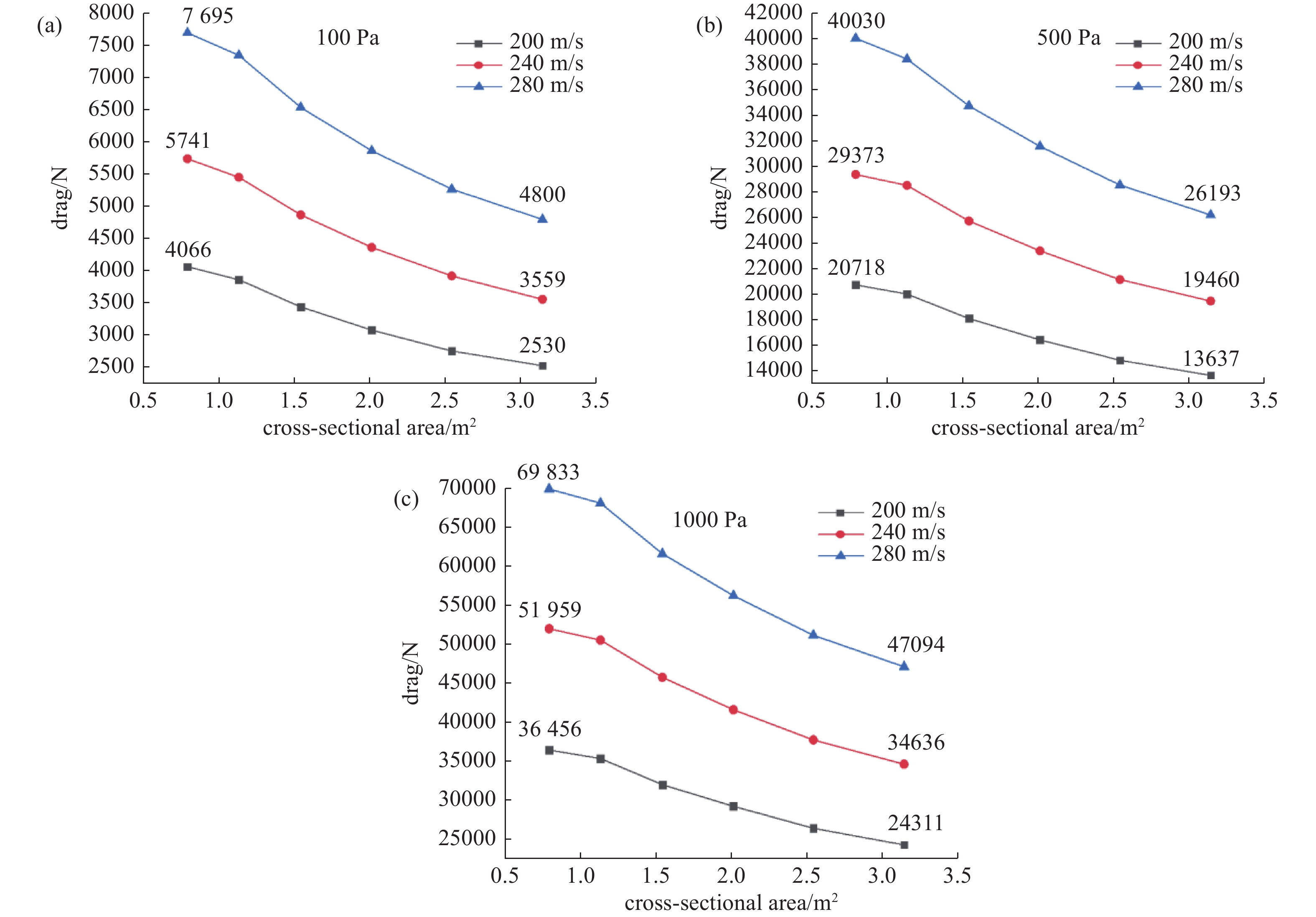
图 12 运行阻力随横通管道横截面积大小的变化关系。(a)管内压力100 Pa, (b)管内压力500 Pa, (c)管内压力1000 Pa
Figure 12. Variation of running resistance with the size of the cross-sectional area of the cross passage. (a) Pressure in the pipe 100 Pa, (b) pressure in the pipe 500 Pa, (c) pressure in the pipe 1000 Pa
表 1 单一管道系统和带横通管道系统列车首尾压差及运行阻力
Table 1. Differential pressure between head and tail of trains and running resistance for single tube systems and systems with cross passages
运行速度/
(m/s)无横通管道
首尾压差/Pa有横通管道
首尾压差/Pa无横通管道
运行阻力/N有横通管道
运行阻力/N200 320 176 4945 2859 240 362 250 7042 4053 280 577 337 9302 5455  下载: 导出CSV
表 2 列车的基本外形尺寸
Table 2. Basic dimensions of the train
尺寸
参数车体最大
高度/m车体最大
宽度/m头车、尾车
长度/m中车
长度/m三节车组
长度/m中国CRH 3.7 3.38 26 25 77
下载: 导出CSV
表 3 带横通管道的真空管道交通系统网格无关性验证
Table 3. Verification of grid independence of vacuum tube transportation systems with cross-pass pipes
列车最大网格
尺寸/m流体域最大网格
尺寸/m网格
节点数网格
总数列车运行
阻力/N0.5 1 56812 251178 4239 0.4 0.8 99451 472143 4290 0.3 0.8 181543 851411 4053 0.2 0.8 214648 1038475 4066
下载: 导出CSV
-
[1] Lowndes I S,Yang Z Y,Jobling S,et al. A parametric analysis of a tunnel climatic prediction and planning model[J]. Tunnelling & Underground Space Technology Incorporating Trenchless Technology Research,2006,21(5):520−532 [2] Sasmito A P,Birgersson E,Ly H C,et al. Some approaches to improve ventilation system in underground coal mines environment - a computational fluid dynamic study[J]. Tunnelling & Underground Space Technology,2013,34(1):82−95 [3] Torno S,Toraño J,Ulecia M,et al. Conventional and numerical models of blasting gas behaviour in auxiliary ventilation of mining headings[J]. Tunnelling & Underground Space Technology,2013,34(34):73−81 [4] Yuan F D,You S J. CFD simulation and optimization of the ventilation for subway side-platform[J]. Tunnelling & Underground Space Technology Incorporating Trenchless Technology Research,2007,22(4):474−482 [5] Eftekharian E,Dastan A,Abouali O,et al. A numerical investigation into the performance of two types of jet fans in ventilation of an urban tunnel under traffic jam condition[J]. Tunnelling & Underground Space Technology,2014,44(3):56−67 [6] Musto M,Rotondo G. Numerical comparison of performance between traditional and alternative jet fans in tiled tunnel in emergency ventilation[J]. Tunnelling & Underground Space Technology,2014,42(42):52−58 [7] Kwon H B,Park Y W,Lee D H. Wind tunnel experiments on korean high-speed trains using various ground simulation techniques[J]. Journal of Wind Engineering and Industrial Aerodynamics,2001,89(13):1179−1195 doi: 10.1016/S0167-6105(01)00107-6 [8] Baron A,Mossi M,Sibilla S. The alleviation of the aerodynamic drag and wave effects of high-speed trains in very long tunnels[J]. Journal of Wind Engineering & Industrial Aerodynamics,2001,89(5):365−401 [9] 贾文广. 真空管道交通系统热动力学特性研究[D]. 青岛: 青岛科技大学, 2013. JIA Wenguang.The characteristic investigation of evacuated tube transport system on thermodynamics[D]. Qingdao: Qingdao University of Science and Technology, 2013. [10] 王海洋. 真空管道交通系统高速运行时的气动特性和能耗分析[D]. 长沙: 湖南大学, 2018. WANG Haiyang.Analysis of aerodynamic characteristics and energy consumption of vacuum pipeline transportation system during high-speed operation[D]. Changsha: Hunan University, 2018. [11] 何德禄. 真空管道车辆抽吸系统减阻机理与能耗分析[D]. 长沙: 湖南大学, 2019. He Delu.Drag reduction mechanism and energy consumption analysis of vacuum pipeline vehicle suction system[D]. Changsha:Hunan University,2019. [12] Hu Xiao,Deng Zigang,Zhang Weihua. Effect of cross passage on aerodynamic characteristics of super-high-speed evacuated tube transportation[J]. Journal of Wind Engineering & Industrial Aerodynamics,2021,211:104562 [13] Wu Ke, Cui Shuaishuai, Zhang Qianjin, et al. Mechanical mechanism analysis and influencing factors of subway cross passage construction[J]. Latin American Journal of Solids and Structures, 2019, 16(6). [14] Zhang Jinghua,Yuan Yong,Bao Zhen,et al. Shaking table tests on the intersection of cross passage and twin tunnels[J]. Soil Dynamics and Earthquake Engineering,2019:124 [15] Yoo,Cui Shuaishuai,Wu Ke,et al. Mechanical mechanism of main tunnels and cross passage construction-A 3D numerical investigation[J]. Journal of the Korean Geosynthetics Society,2019,18(1):11−23 [16] 王凯. 基于热压循环通道的真空管道交通系统气动及热力学特性研究[D]. 青岛: 青岛科技大学, 2018 Wang Kai. Aerodynamic and thermodynamic properties in the vacuum tube transportation system based on heat and pressure recycle ducts[D].Qingdao: Qingdao University of Science and Technology,2018. [17] 张亮. 高速列车气动外形优化设计研究[D]. 成都: 西南交通大学, 2017. Zhang Liang. Study on Aerodynamic Shape Optimization Design of High-speed Trains[D]. Chengdu:Southwest Jiaotong University, 2017. [18] 张勇. 低真空管道磁浮运输系统气动特性仿真研究[D]. 成都: 西南交通大学, 2019. Daniel Zhang. Study on aerodynamic characteristics of maglev transport system with a low-Pressure tube[D]. Chengdu:Southwest Jiaotong University, 2019. [19] ZHANG Kerui,LI Qingling,WANG Chuanwei,et al. Aerodynamic noises of vacuum tube transportation: a simulation and theoretical study[J]. journal of vacuum science and technology,2019,39(11):950−957 (张克锐,李庆领,王传伟 等. 真空管道高速列车气动噪声研究[J]. 真空科学与技术学报,2019,39(11):950−957(in chinese) ZHANG Kerui,LI Qingling,WANG Chuanwei,et al.Aerodynamic noises of vacuum tube transportation: a simulation and theoretical study journal of vacuum science and technology,2019,39(11):950-957. [20] 刘海龙. 真空管道交通系统综合运行能耗的研究[D]. 青岛: 青岛科技大学, 2016. Liu Hailong. Research on comprehensive energy consumptionin of the evacuated tube transport system[D]. Qingdao: Qingdao University of Science and Technology, 2016. [21] LIU Jiali,ZHANG Jiye,ZHANG Weihua. Impacts of pressure,blockage-ratio and speed on aerodynamic drag-force of high-speed trains[J]. Journal of Vacuum Science and Technology,2014,34(01):10−15 (刘加利,张继业,张卫华. 真空管道高速列车气动阻力及系统参数设计[J]. 真空科学与技术学报,2014,34(01):10−15(in chinese) LIU Jiali,ZHANG Jiye,ZHANG Weihua.Impacts of pressure,blockage-ratio and speed on aerodynamic drag-force of high-speed trains[J].Journal of Vacuum Science and Technology,2014,34(01):10-15. [22] Kim Tae-Kyung,Kim Kyu-Hong,Kwon Hyeok-Bin. Aerodynamic characteristics of a tube train[J]. Journal of Wind Engineering & Industrial Aerodynamics,2011,99(12):1187−1196 [23] HUANG Zundi,LIANG Xifeng,CHANG Ning. Analysis on simulation algorithm for train outflow field of vacuum pipeline traffic[J]. Journal of Engineering Thermophysics,2018,39(06):1244−1250 (黄尊地,梁习锋,常宁. 真空管道交通列车外流场仿真算法分析[J]. 工程热物理学报,2018,39(06):1244−1250(in chinese) HUANG Zundi, LIANG Xifeng, CHANG Ning.Analysis on simulation algorithm for train outflow field of vacuum pipeline traffic[J].Journal of Engineering Thermophysics,2018,39(06):1244-1250. [24] 张克锐. 受限空间内高速列车流线结构优化及气动特性分析[D]. 青岛: 青岛科技大学, 2020. Zhang Kerui. Streamline structure optimization and aerodynamic characteristics analysis of high-speed trains in confined spaces[D]. Qingdao: Qingdao University of Science and Technology, 2020. [25] 方晨宇. CRH380B型高速列车空气动力噪声的数值模拟研究[D]. 兰州: 兰州交通大学, 2019. FANG Chenyu.Numerical simulation of aerodynamic noise of CRH380B high speed train[D]. Lanzhou: Lanzhou Jiaotong University, 2019. [26] WANG Haiming,LI Qingling,JIA Wenguang. Study on the variation of the average differential pressure between the head and tail of high-speed trains in vacuum tube[J]. Journal of Vacuum Science and Technology,2021,41(12):1164−1170 (王海明,李庆领,贾文广. 真空管道高速列车首尾平均压差变化规律研究[J]. 真空科学与技术学报,2021,41(12):1164−1170(in chinese) WANG Haiming,LI Qingling,JIA Wenguang. Study on the variation of the average differential pressure between the head and tail of high-speed trains in vacuum tube[J] Journal of Vacuum Science and Technology,2021,41(12):1164-1170. [27] HUANG Zundi,LIANG Xifeng,CHANG Ning. Numerical analysis of train aerodynamic drag of vacuum tube traffic[J]. Journal of Mechanical Engineering,2019,55(08):165−172 (黄尊地,梁习锋,常宁. 真空管道交通列车气动阻力数值分析[J]. 机械工程学报,2019,55(08):165−172(in chinese) HUANG Zundi, LIANG Xifeng, CHANG Ning. Numerical analysis of train aerodynamic drag of vacuum tube traffic[J].Journal of Mechanical Engineering,2019,55(08):165-172. -
计量
- 文章访问数: 492
- HTML全文浏览数: 492
- PDF下载数: 4
- 施引文献: 0