
 首页
首页 登录
登录 注册
注册


 下载:
下载:
-
The ionization gauge is a device for measuring vacuum pressure. It is used to obtain the pressure indirectly by measuring the positive ion current generated by electrons colliding with gas molecules[1]. At present, the commercial cold cathode ionization gauges have a lower measurement limit of 10−9 Pa and the hot cathode ones have a lower measurement limit of 10−12 Pa. In 2021, PTB proposed a novel design to develop a high-precision ionization gauge[2], where the electron trajectories in the ionization region are fixed and only pass through the ionization region once. The emitted electrons pass through the ionization region and are collected by the Faraday cup at the end, which does not produce secondary electrons, and the electron transmission efficiency is 100%. All the ions in the ionization region are collected, and the ion collection efficiency is 100%. Performance investigation of this ionization gauge prototype show that the gauge exhibits good linearity over the measurement range of 10−6 to 10−2 Pa, with sensitivity fluctuations of ±0.5%[3]. Considering that the hot cathode has the high power consumption and thermal irradiation[4]. The carbon nanotubes (CNT) are regarded as ideal field emission cathode materials due to their high aspect ratio, mechanical strength, and low thermal disturbance[5]. Therefore, we combine a CNT electron source with the novel measurement electrodes optimized based on the basic structure proposed by Karl Jousten et al. The specific simulation design is described in reference [6]. The simulated sensitivity is 0.250 Pa−1 when the background gas is nitrogen, which is expected to further enhance the measurement performance of the highly stable ionization gauge.
-
The highly stable ionization gauge achieves stable control of electron paths and kinetic energies by means of an electric field formed by several lens. In order to ensure the stability of the sensitivity, the emission characteristics of the electron source are crucial, so it is first necessary to carry out the morphological observation as well as the experimental tests of diode-type structure, triode-type structure and short-term emission stability of the prepared CNT cathode.
The CNT electron source was prepared by Wenzhou University using thermal chemical vapor deposition on a stainless steel substrate with the diameter of 1 mm, and its specific preparation process was described in the literature[7]. Sigma 500 high-resolution and high-precision scanning electron microscope was utilized to observe the surface morphology of CNT. As can be seen in Fig.1, the nanotubes prepared were entangled with each other, oriented randomly, with the diameter of about 40 nm ~ 60 nm, and the length of about a few tens of micrometers. The black dot present in the Fig.1(a) is due to the fact that a set of experiments had already been done on this CNT electron source prior to morphology analyzation. Normally, the black dot means the loss of the CNT caused by the joule heating or the ion bombardment.
The CNT cathode was fixed on the base when assembling the compact structure of the gauge prototype, and the tungsten mesh with wire diameter of 50.9 μm and 100 mesh was used as the gate. The spacing between the CNT cathode and the gate was controlled with ceramic spacers at 180 μm ~ 200 μm. The prototype and circuit diagram of the highly stable ionization gauge are shown in Fig.2. In order to prevent the circuit from damaging the CNT, the cathode was grounded after connecting a resistor of 10 kΩ in series.
In testing the sensitivity of the ionization gauge, an UHV/XHV calibration system[8] was used, with the background pressure in the level of 10−7 Pa. The standard pressure was provided using the dynamic flow method. The nine pressure points were taken to record the individual electrodes currents in the level of 10−6 Pa ~ 10−5 Pa, and the sensitivity values under different pressure points were obtained by the sensitivity calculation formula (1)[9]. Here, ΔI+ is the change of the ion current I+ at the ion collector before and after the introduction of the experimental gas into the calibration chamber, and I− is the collected electron current, and the pstd is the standard pressure.
-
In order to understand the emission properties of CNT cathode, the prepared CNT cathode was first tested in diode-type and triode-type experiments. Fig.3 demonstrates to the emission properties and stability results for CNT cathode. The diode-type experimental set-up was consisted of the CNT cathode and anode, in which the anode received electrons with a stainless steel disc, and the spacing between the two electrodes was controlled by ceramic spacer at 200 μm. The anode voltage was adjusted under a pressure of 1.99×10⁻⁵ Pa. The cathode emission current, the anode current and their fitting curves are recorded in Fig.3(a). When the potential difference between the cathode and the anode reaches 400 V, the CNT cathode starts to emit electron current of 0.1 μA, and while the anode voltage increases to 1000 V, cathode emission current reaches 128.8 μA. Basically all of the emission current is received by the anode. The fitting curves of the cathode and the anode currents are in good agreement. The experiments are repeated to plot the J-E curve of the emission current density versus the applied electric field, as well as the F-N curves (Fig.3(b)) As seen from the figure, the turn-on field strength of the carbon nanotubes used in the experiments is 2 V/μm, and the emission current density reaches 15.06 mA/cm2 when the field strength is increased to 4.85 V/μm. The field enhancement factor is calculated to be 10362.77, based on the Fowler-Nordheim (F-N) theory[10] combined with the data from the two sets of experiments.
In the triode-type experimental test, the cathode voltage was set to 0 V, the anode voltage was set to 1520 V, and the gate voltage was adjusted in the range of 0 to 1500 V. The test was carried out at a pressure of 2×10⁻⁵ Pa. The results obtained are shown in Fig.3(c), where the CNT cathode starts to emit electrons when the gate voltage is set at 600 V, and the anode current could be obtained when the gate voltage is higher than 620 V. The cathode emission current and anode current gradually increases along with the rise of the gate voltage. The emission current and anode current could reach 54.3 μA and 33 μA with the gate voltage of 1500 V, respectively.
The short-term stability of CNT emission was also investigated. The cathode emission current, gate current and anode current were tested over a period of 390 mins without stable current circuit. During the test, the cathode voltage, gate voltage and anode voltage were fixed at 0 V, 1400 V and 1500 V, respectively. The test vacuum pressure was 1×10⁻⁵ Pa. The results obtained are shown in Fig.3(d), where the emission current is in the range of 30.3 μA ~ 39.2 μA, the anode current ranges from 19.1 μA to 26.5 μA, and the electron transmission efficiency is maintained between 61.6% and 69.3%. It showed that CNT have stable emission and can be used as an electron source.
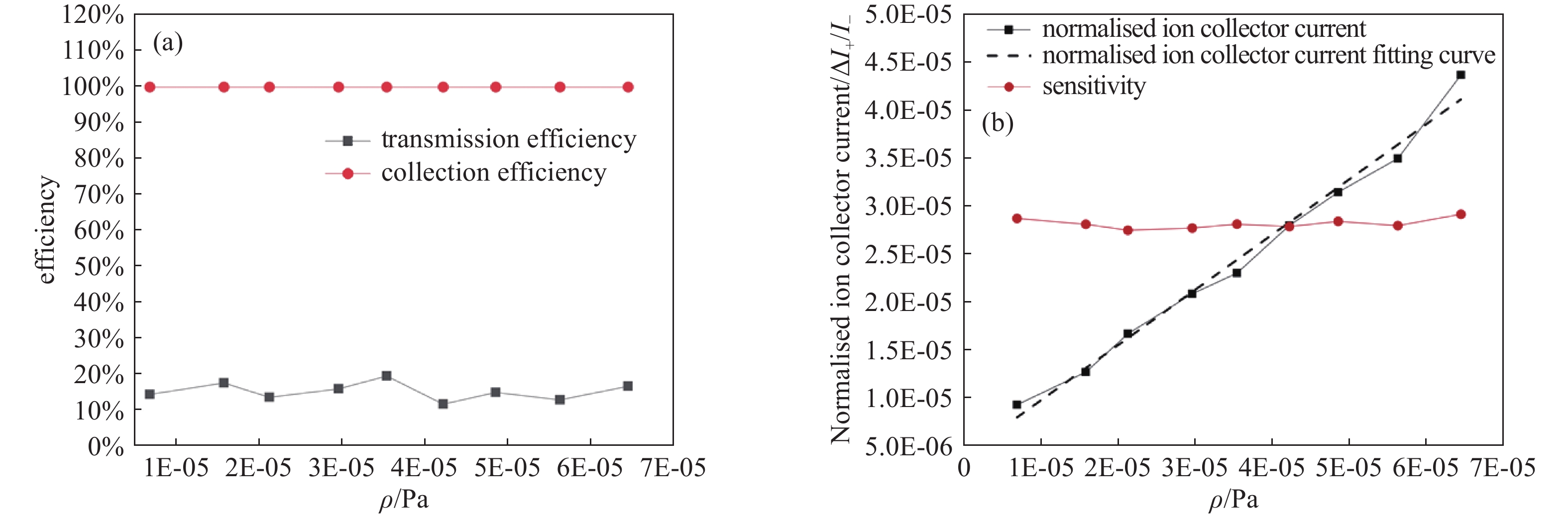
The triode-type electron source mentioned above was applied to the experimental testing of the gauge prototype. Based on the electrodes voltages optimization[6], the voltages of the cathode, gate, deceleration electrode, focusing electrode, inlet frame, ionization chamber, ions collector, electrons collector and deflection electrode were set as 0, 1600, 500, 1500, 500, 250, 0, 800, 0 V, respectively. The background pressure of the calibration chamber was 8.47×10⁻⁷ Pa. The gauge was calibrated in the range of 6.87×10⁻⁶ Pa ~ 6.45×10⁻⁵ Pa. As shown in Fig.4, the variation of the electron transmission efficiency and electron collection efficiency were recorded, and linearity correlation between the vacuum pressure and the normalized ion collection current was also investigated as well.
From Fig.4(a), it can be seen that the electron transmission efficiency is between 11.69% and 17.59%, and the electron collection efficiency is 100%, which is consistent with the simulation results[11].
From Fig.4(b), it can be seen that the normalized ion collection current is basically linear to the vacuum pressure, where the normalized ion current represents the ratio of the collected ion current to the collected electron current. The experimental sensitivities are also calculated for each calibration pressure point. From 6.87×10⁻⁶ Pa to 6.45×10⁻⁵ Pa, the sensitivity fluctuates in the range of 0.200 Pa−1 ~ 0.245 Pa−1. According to formula (2), the sensitivity fluctuation is less than 5.96%.
Here,
$ \sigma $ is the sensitivity fluctuation, i is the number of tests, Si is the sensitivity of the calibration point, and$ \overline S $ is the average experimental sensitivity.The deviation of the experimental results with the simulated sensitivity of 0.250 Pa−1 is up to 20%. The variation of the sensitivity might be caused by the unstable electron transmission efficiency and the uncontrolled electron emission, which would be improved in further optimization.
-
The experimental results on the ionization gauge show that all the electrons entering the ionization chamber are received by the electron collector, which indicates that the CNT electron source applied to the highly stable ionization gauge can also realize the collimation and focusing of the electron beam. The experimental sensitivity fluctuates in the range of 0.200 Pa−1 ~ 0.245 Pa−1, and the deviation with the simulated sensitivity of 0.250 Pa−1 is up to 20%, and the sensitivity fluctuation is less than 5.96%, which indicates that the design is reasonable and feasible.
However, regarding to the factors such as the emission stability of CNT, mechanical inaccuracy, and electric circuit, there will be some optimizations to be done to improve the sensitivity stability. It is expected to be applied to ultrahigh vacuum calibration or the fields requiring precise measurement.
基于碳纳米管电子源的高稳定电离真空计的性能研究
Performance Investigation of a Highly Stable Ionization Gauge Based on Carbon Nanotube Electron Source
-
摘要: 文章将碳纳米管电子源应用于高稳定电离真空计,通过结构和电参数优化,研制了样机,并开展了样机计量特性的实验研究,研究结果表明,新型电离规在6.87×10⁻⁶ Pa ~ 6.45×10⁻⁵ Pa的压力范围内,灵敏度在0.200 Pa−1 ~ 0.245 Pa−1的范围内波动,与仿真灵敏度0.250 Pa−1的偏差最大为20%,灵敏度波动小于5.96%,证明该结构设计合理,有望应用于超高真空校准及精确测量领域。Abstract: In this paper, a carbon nanotube electron source is applied to a highly stable ionization gauge, and a preliminary performance experimental study of the prototype is carried out. The results show that the sensitivity of the novel ionization gauge fluctuates in the range of 0.200 Pa−1 ~ 0.245 Pa−1 from 6.87×10⁻⁶ Pa to 6.45×10⁻⁵ Pa, with a maximum deviation of 20% from the simulated sensitivity of 0.250 Pa−1, and the sensitivity fluctuation is less than 5.96%, which proves that the structure is well-designed and is expected to be applied to high vacuum calibration and precise measurement.
-
Key words:
- Carbon nanotube electron source /
- Ionization gauge /
- Sensitivity .
-

-
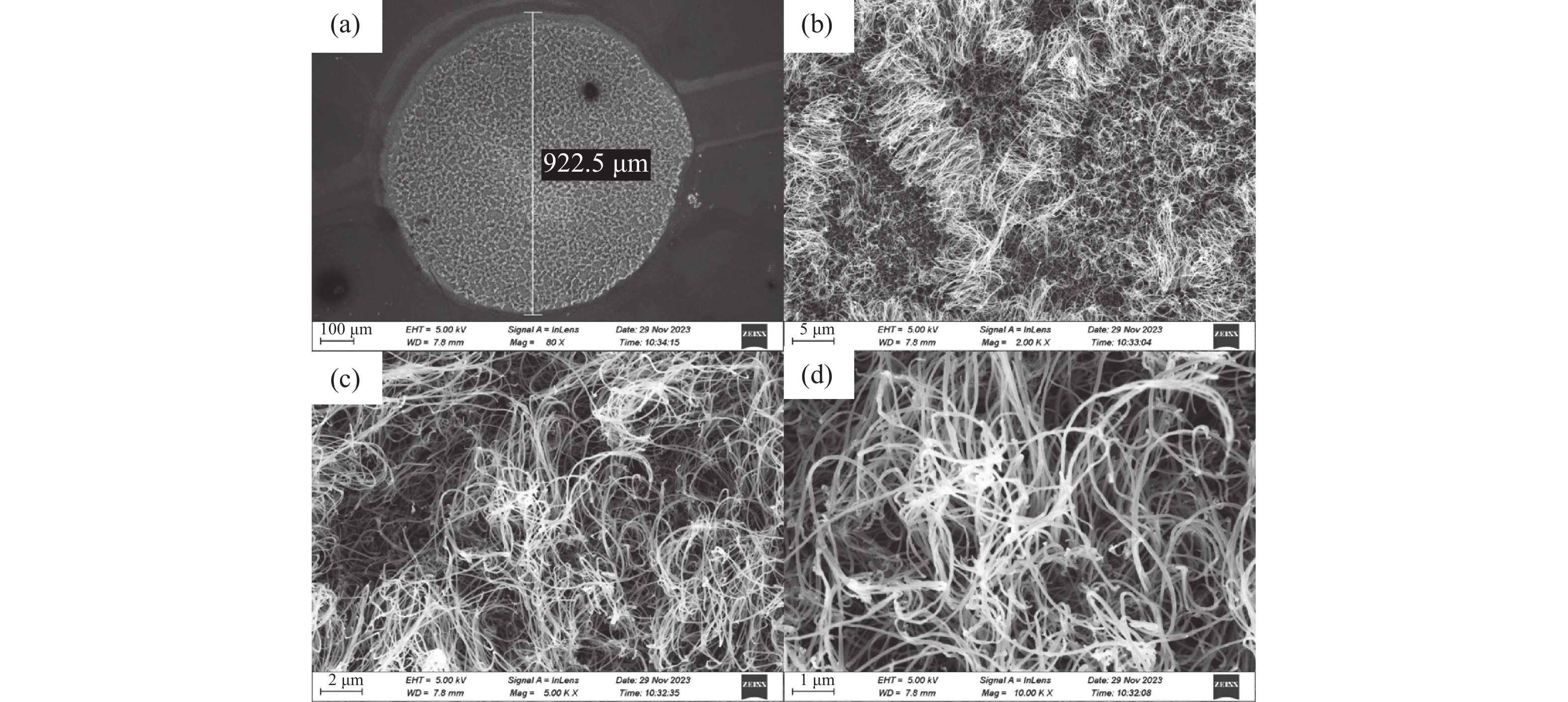
图 1 碳纳米管的形貌。(a) 100 μm 尺寸的 CNT 扫描电镜图像,(b) 5 μm 尺寸的 CNT 扫描电镜图像,(c) 2μm 尺寸的 CNT 扫描电镜图像,(d)1 μm 尺寸的 CNT 扫描电镜图像
Figure 1. Morphology of carbon nanotubes. (a) The SEM image of the CNTs at 100 μm scale, (b) the SEM image of the CNTs at 5 μm scale, (c) the SEM image of the CNTs at 2 μm scale, (d) the SEM image of the CNTs at 1 μm scale
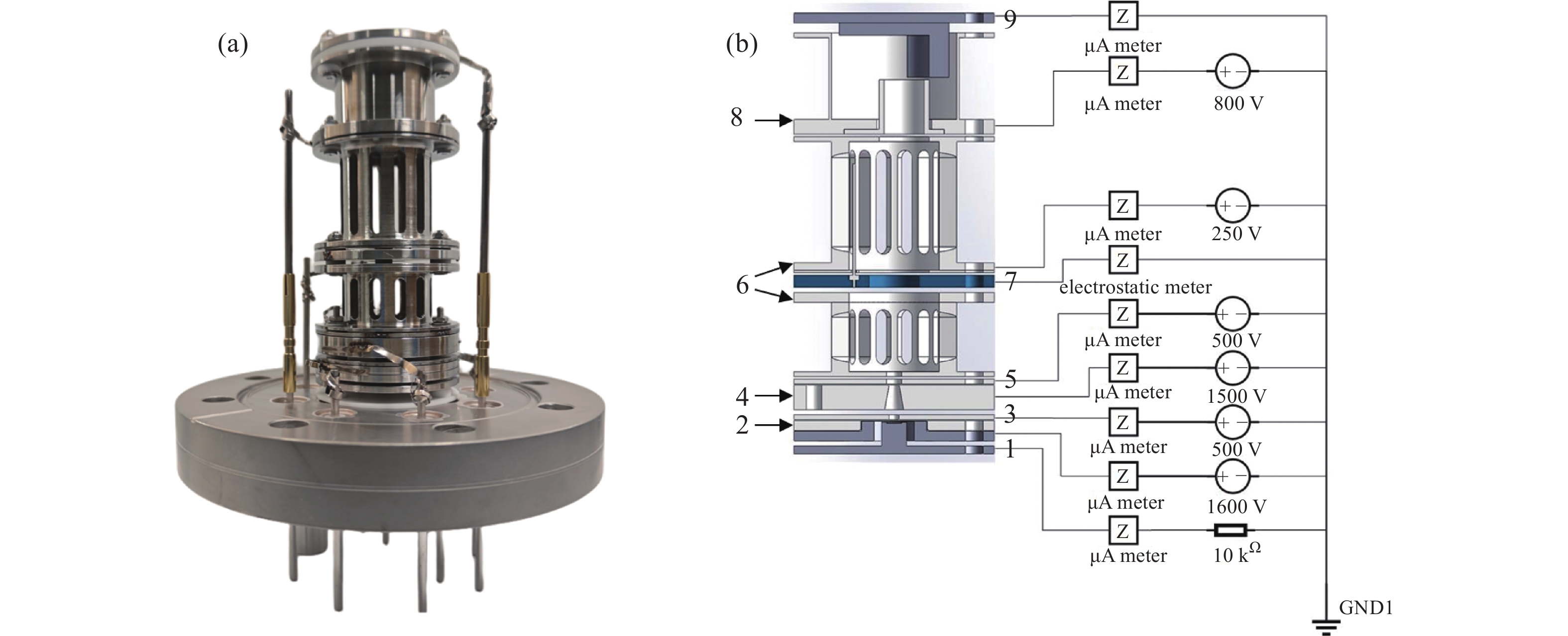
图 2 高稳定电离真空规样机和电路图。 (a)样机,(b)电路图(1:CNT阴极 2:门极 3:减速极 4:聚焦极 5:入口栅 6:电离室 7:离子收集极 8:电子收集极 9:偏转极)
Figure 2. Prototype and circuit diagram of the highly stable ionization gauge. (a) Prototype, (b) circuit diagram (1: CNT cathode 2:gate 3: deceleration electrode 4: focusing electrode 5: inlet frame 6: ionization chamber 7: ion collector 8: electron collector 9: deflection electrode)
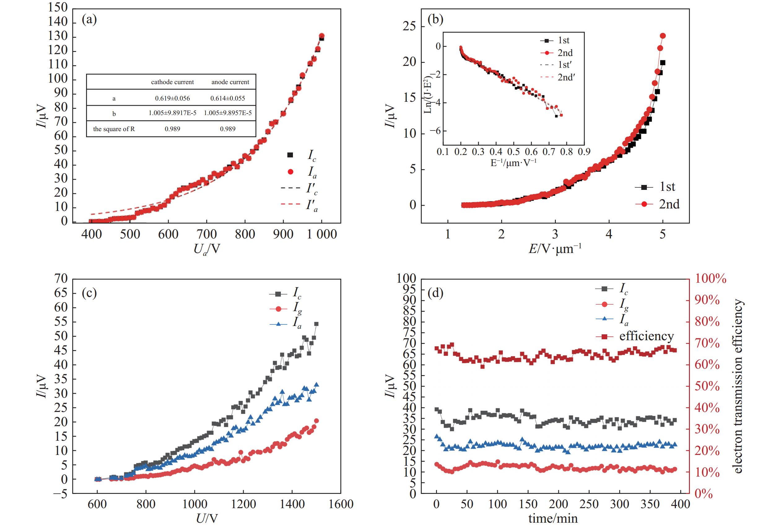
图 3 碳纳米管阴极的发射特性和稳定性结果。(a)二极式结构的I-V特性曲线,(b)二极式结构的J-E特性曲线和F-N曲线,(c)三极式结构中阴极电流、门极电流和阳极电流随门极电压的变化曲线,(d)三极式结构中场发射阴极的发射稳定性测试(Ic代表碳纳米管阴极的发射电流,Ig代表门极电流,Ia代表阳极电流)
Figure 3. The emission properties and stability results of the CNT cathode. (a) I-V characteristic curve of diode-type structure, (b) J-E characteristic curve and F-N curve of diode-type structure, (c) curves of cathode current, gate current and anode current with gate voltage in triode-type structure, (d) emission stability tests of field emission cathodes in triode-type structures (Ic represents the current at the cathode of the carbon nanotube, Ig represents the gate current, and Ia represents the anode current)
-
[1] Li D, Wang Y, Cheng Y, et al. The recent development of ionization gauge with carbon nanotube cathode[J]. Vacuum,2014,51(04):26−30 [2] Jenninger B, Anderson J, Bernien M, et al. Development of a design for an ionisation vacuum gauge suitable as a reference standard[J]. Vacuum,2021,183:109884 doi: 10.1016/j.vacuum.2020.109884 [3] Jousten K, Bernien M, Boineau F, et al. Electrons on a straight path: A novel ionisation vacuum gauge suitable as reference standard[J]. Vacuum,2021,189:110239 doi: 10.1016/j.vacuum.2021.110239 [4] Li D, Zhang H, Feng Y, et al. The fabrication and research progress of field emission cathode for vacuum measurement[J]. Vacuum & Cryogenics,2013,19(01):1−6 doi: 10.3969/j.issn.1006-7086.2013.01.001 [5] 张建. 强附着碳纳米管CVD生长技术及场致发射应用研究[D]. 温州大学, 2016. (in Chinese) Zhang J. Investigation on growth and characterization techniques of CNTs with strong adhension antits field emission application[D]. Wenzhou University, 2016 [6] Ma Z, Zhang H, Li D, et al. Numerical simulation of a metrological ionization vacuum gauge based on carbon nanotube electron source[J]. Vacuum & Cryogenics,2023,29(03):243−250 doi: 10.3969/j.issn.1006-7086.2023.03.006 [7] Zhang H, Li D, Wurz P, et al. Performance of a low energy ion source with carbon nanotube electron emitters under the influence of various operating gases[J]. Nanomaterials,2020,10(2):354 doi: 10.3390/nano10020354 [8] Li D, Cheng Y, Feng Y, et al. Latest progress in calibrations of ultra-high vacuum and extreme high vacuum[J]. Chinese Journal of Vacuum Science and Technology,2009,29(06):641−648 [9] Bundaleski N, Adame C F, Bernien M, et al. Novel ionisation vacuum gauge suitable as a reference standard: influence of primary electron trajectories on the operation[J]. Vacuum,2022,201:111041 doi: 10.1016/j.vacuum.2022.111041 [10] Parveen S, Kumar A, Husain S, Fowler Nordheim, et al. Theory of carbon nanotube based field emitters[J]. Physica B:Condensed Matter,2017,505:1−8 doi: 10.1016/j.physb.2016.10.031 [11] Ma Z, Li D, Zhang H, et al. Study of a low-energy collimated beam electron source and its application in a stable ionisation gauge[J]. Vacuum,2023,215:112302 doi: 10.1016/j.vacuum.2023.112302 -
计量
- 文章访问数: 223
- HTML全文浏览数: 223
- PDF下载数: 4
- 施引文献: 0