-
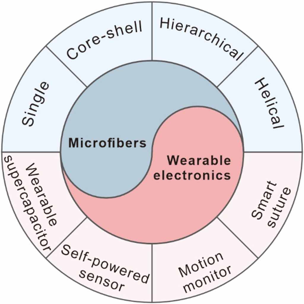
Figure 1. Overview of the microfluidic-derived functional microfibers and their applications in flexible bioelectronics.
-
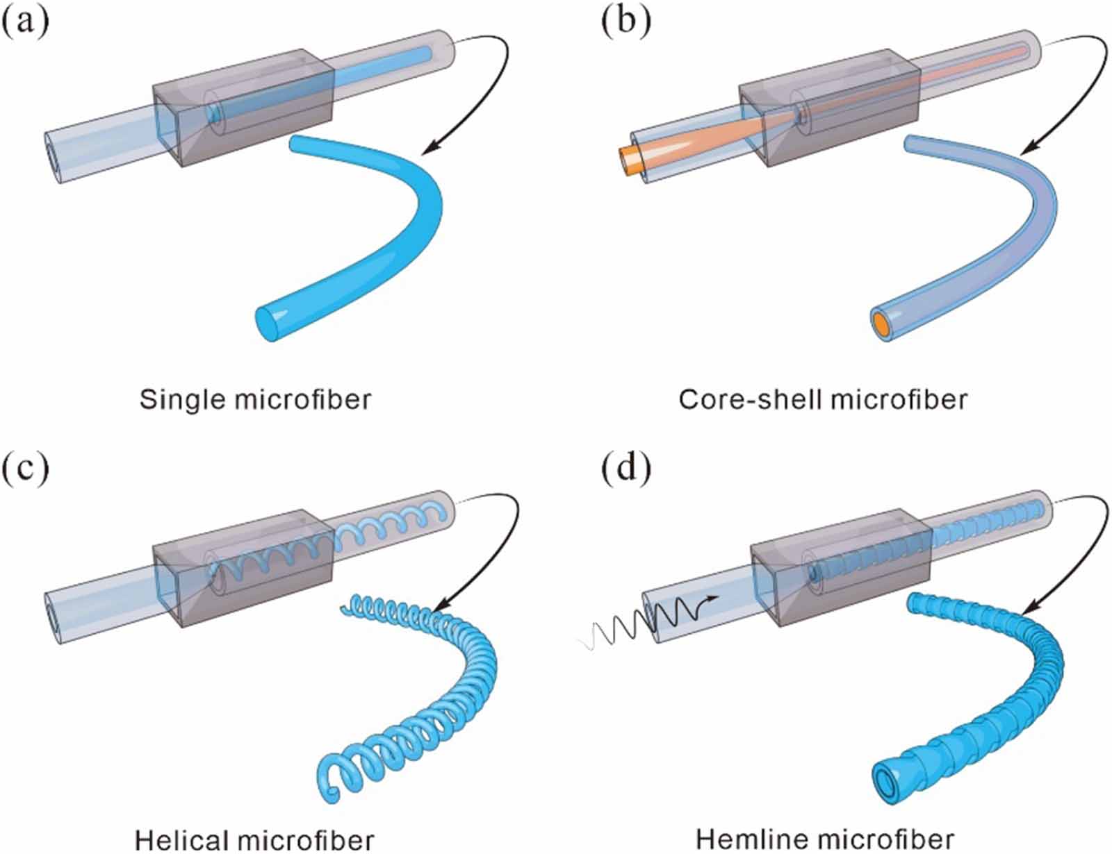
Figure 2. Schematics of the typical preparation process for (a) single, (b) core-shell, (c) helical, and (d) hemline-shaped microfibers using microfluidics.
-
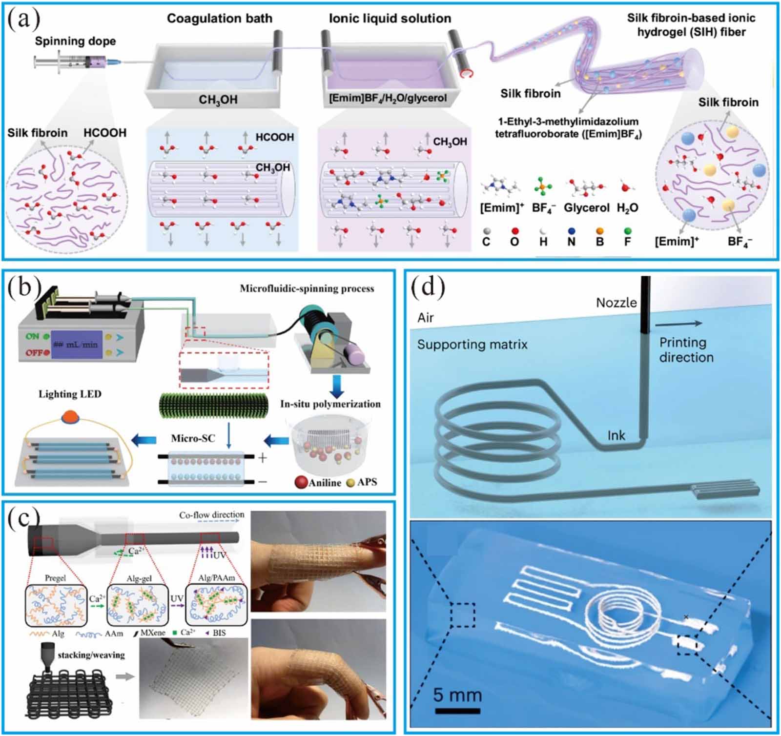
Figure 3. (a) Schematics of the wet-spinning apparatus by directly injecting the homogeneously dispersed phase into a coagulation bath reproduced from [70].
CC BY 4.0 ; (b) schematic illustration of the microfluidic fabrication process with in situ polymerization. [101] John Wiley & Sons. © 2018 WILEY-VCH Verlag GmbH & Co. KGaA, Weinheim; (c) schematic of the microfluidic fabrication of microfibers with gridded structures. Reprinted with permission from [98]. Copyright (2021) American Chemical Society; (d) microfluidic integration with 3D printing for constructing 3D scaffold structures. Reproduced from [112], with permission from Springer Nature. -
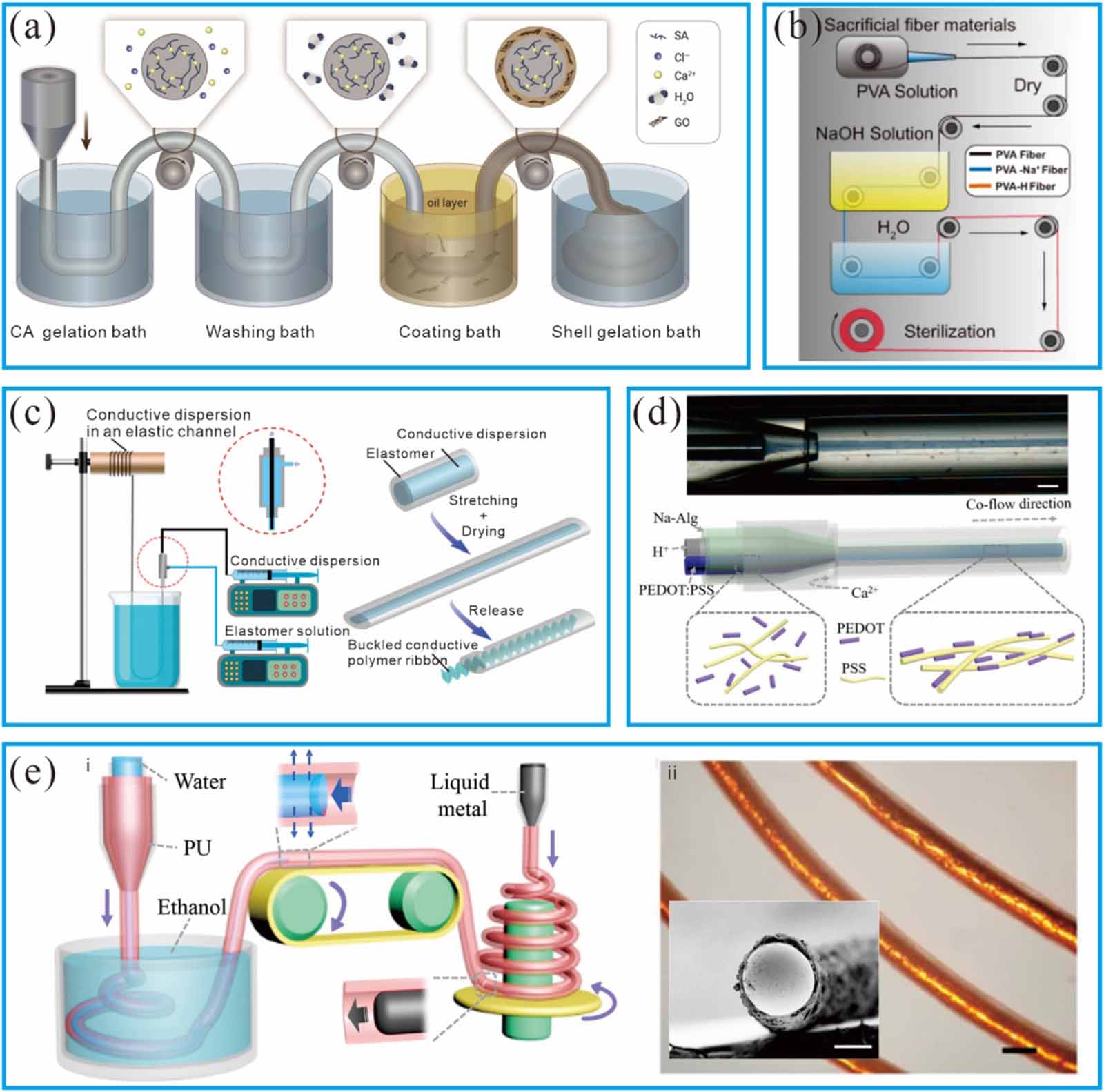
Figure 4. (a) Core-shell microfibers fabricated using microfluidic spinning combined with a coating technique. Reproduced with permission from [103].
CC BY-NC-ND 4.0 ; (b) hollow-channel microfibers created using coaxial spinning involving a sacrificial inner layer. Reproduced from [123].CC BY 4.0 ; (c) conductive microfibers with enhanced mechanical properties fabricated using coaxial spinning combined with a stretching-drying-buckling process. [105] John Wiley & Sons. © 2019 WILEY-VCH Verlag GmbH & Co. KGaA, Weinheim; (d) core-shell microfibers with a PEDOT:PSS core produced entirely through microfluidic spinning. [106] John Wiley & Sons. © 2019 WILEY-VCH Verlag GmbH & Co. KGaA, Weinheim; (e) ultra-elastic microfibers integrated with liquid metal, manufactured using microfluidic coaxial microfluidic spinning. Reprinted from [107], © 2020 Science China Press. Published by Elsevier B.V. and Science China Press. All rights reserved. -
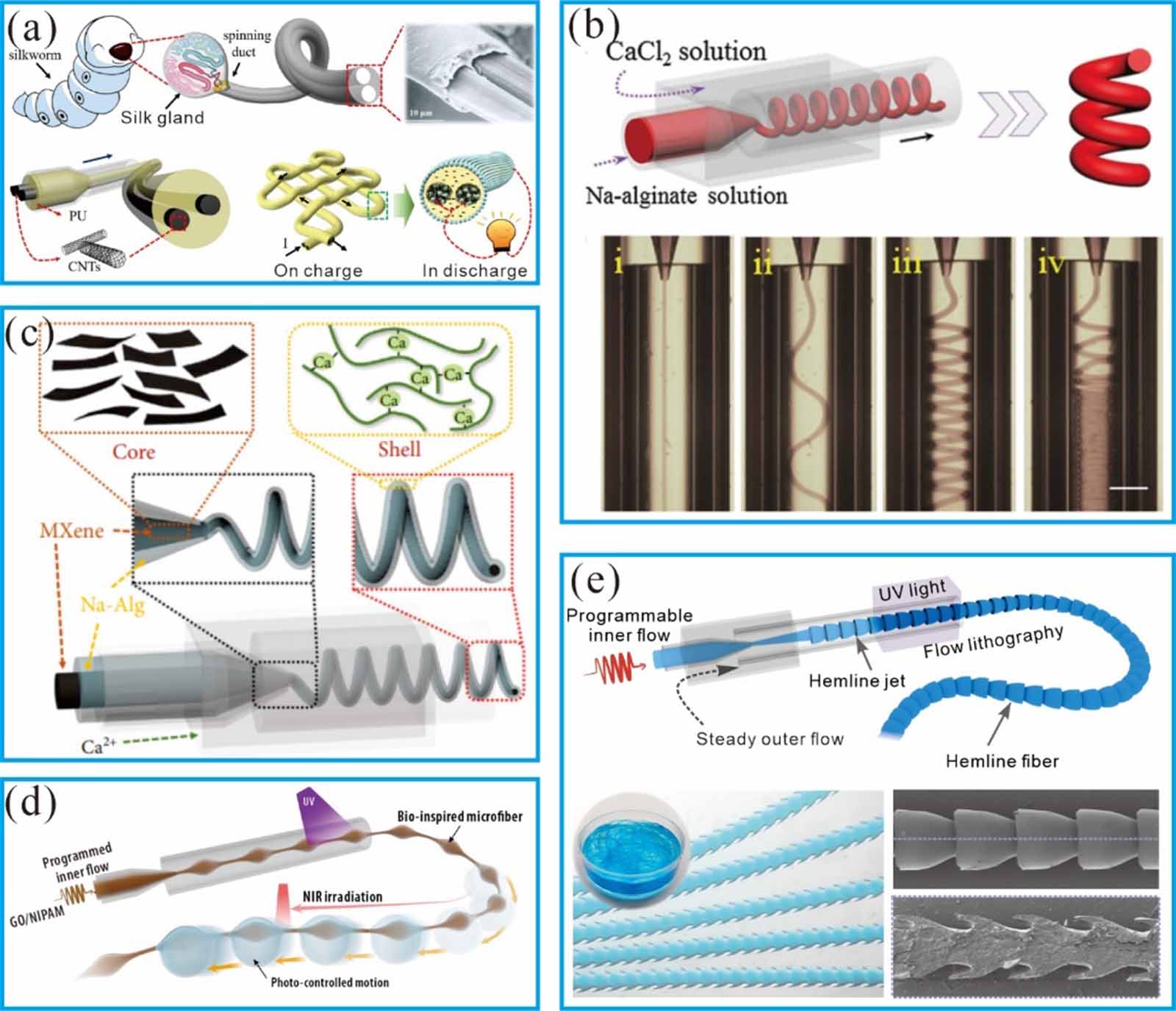
Figure 5. (a) Single-step fabrication of multicomponent carbon nanotubes microfiber by multi-channel co-flow microfluidics. Reprinted from [109], © 2020 Elsevier B.V. All rights reserved; (b), (c) helical microfibers. [110] John Wiley & Sons. © 2017 WILEY-VCH Verlag GmbH & Co. KGaA, Weinheim and MXene encapsulated core-shell helical microfibers from microfluidics by using the rope-coil effect. Reproduced from [111].
CC BY 4.0 ; (d), (e)spindle-knot. Reprinted from [97], © 2022 Elsevier B.V. All rights reserved and hemline-shaped microfibers from piezoelectric microfluidics. Reproduced from [95], with permission from Springer Nature. -
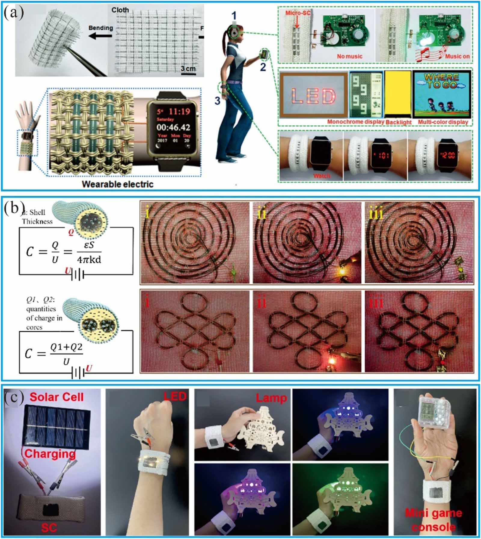
Figure 6. (a) Flexible graphene fiber supercapacitor integration [149]. John Wiley & Sons. © 2017 WILEY-VCH Verlag GmbH & Co. KGaA, Weinheim; (b) carbon nanotube microfiber for energy storage. Reprinted from [109], © 2020 Elsevier B.V. All rights reserved; (c) wearable self-powered device with flexible supercapacitor. Reproduced from [150], with permission from Springer Nature.
-
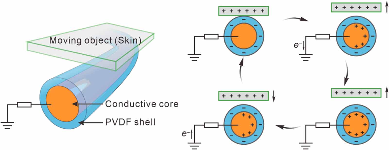
Figure 7. Utilization of sheath-core microfibers/fabrics for self-powered sensor deployment.
-
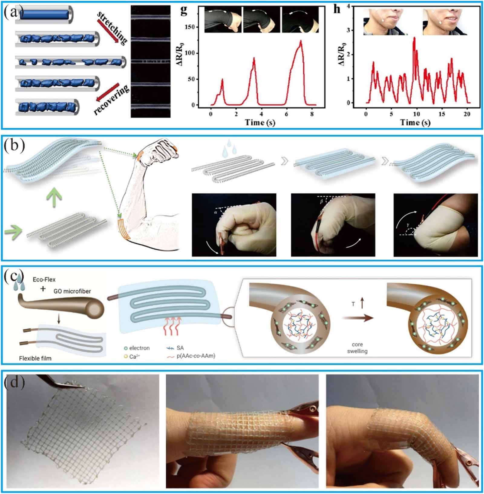
Figure 8. (a) Fiber-based wrist bending detection and facial muscle monitoring. Reprinted from [163], © 2024 Published by Elsevier B.V; (b) spiral fibers embedded within flexible films for joint monitoring. Reproduced from [164].
CC BY 4.0 ; (c) addition of graphene oxide on the outer layer for simultaneous temperature and motion monitoring. Reproduced with permission from [103].CC BY-NC-ND 4.0 ; (d) utilization of 3D-printed grid-like structure for joint sensing. Reprinted with permission from [98]. Copyright (2021) American Chemical Society. -
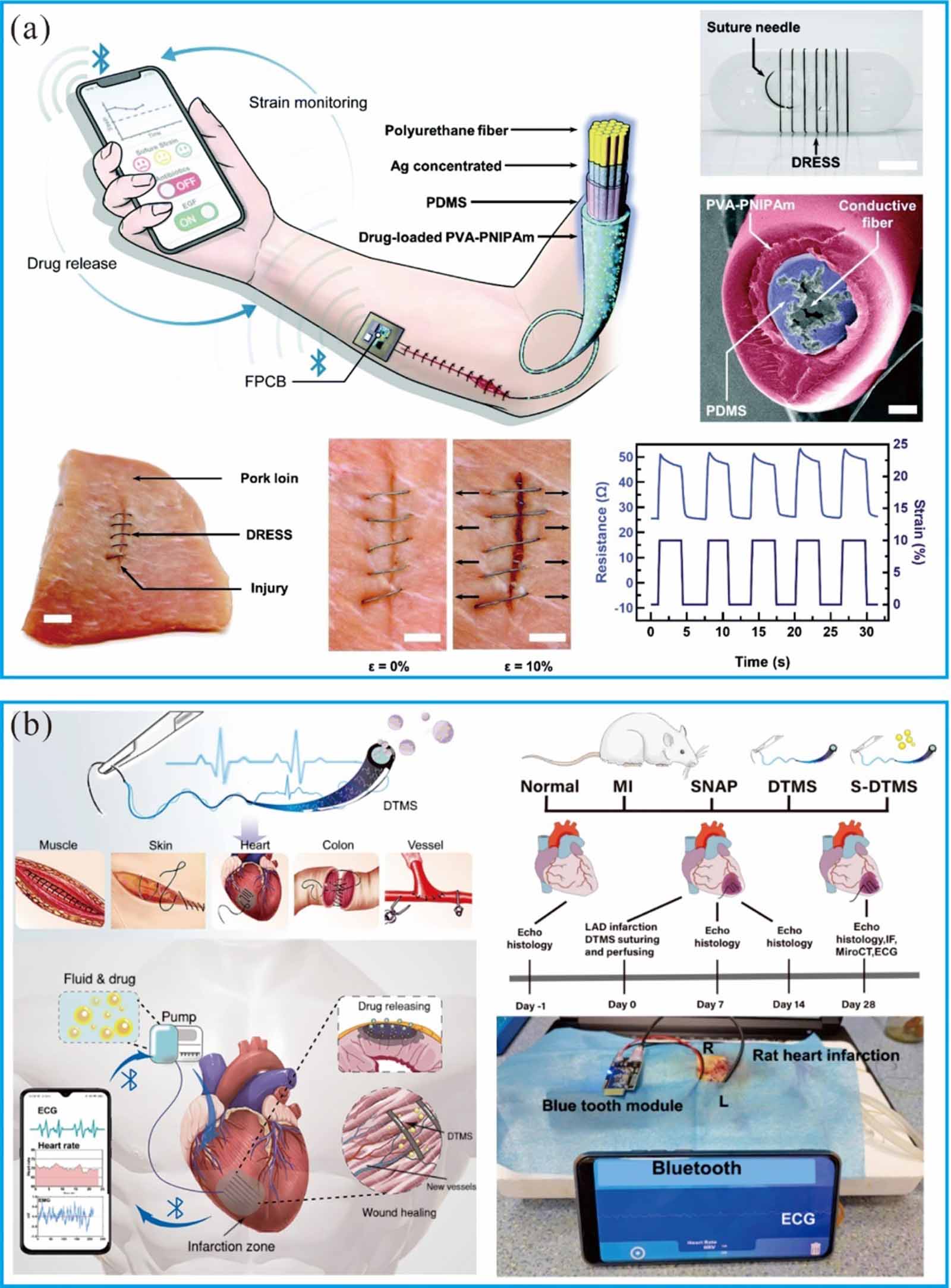
Figure 9. (a) A smart drug-release suture incorporates a core made of conductive fiber strain sensors and a thermoresponsive polymer shell containing medications. Reproduced from [170] with permission from the Royal Society of Chemistry; (b) schematic of the diagnosis, treatment, and monitoring suture applicable to various tissues, capable of transmitting signals from infarcted heart tissue and delivering drugs on demand. Reproduced from [123].
CC BY 4.0 .
Figure
9 ,Table
1 个