-

Figure 1. Design and fabrication of the K-TENG. (a) Schematic illustration of the self-powered system. (b) Schematic diagram of the preparation of PVDF nanofibers by the electrospinning process. (c) Flexibility of the K-TENG. (d) SEM image of the nanofiber PVDF film. Inset shows the hydrophobic property. Two different kirigami patterns of (e) uniaxial K-TENG and (h) biaxial K-TENG. (f) Stretched and (g) twisted uniaxial K-TENG. (i) Stretched and (j) twisted biaxial K-TENG.
-
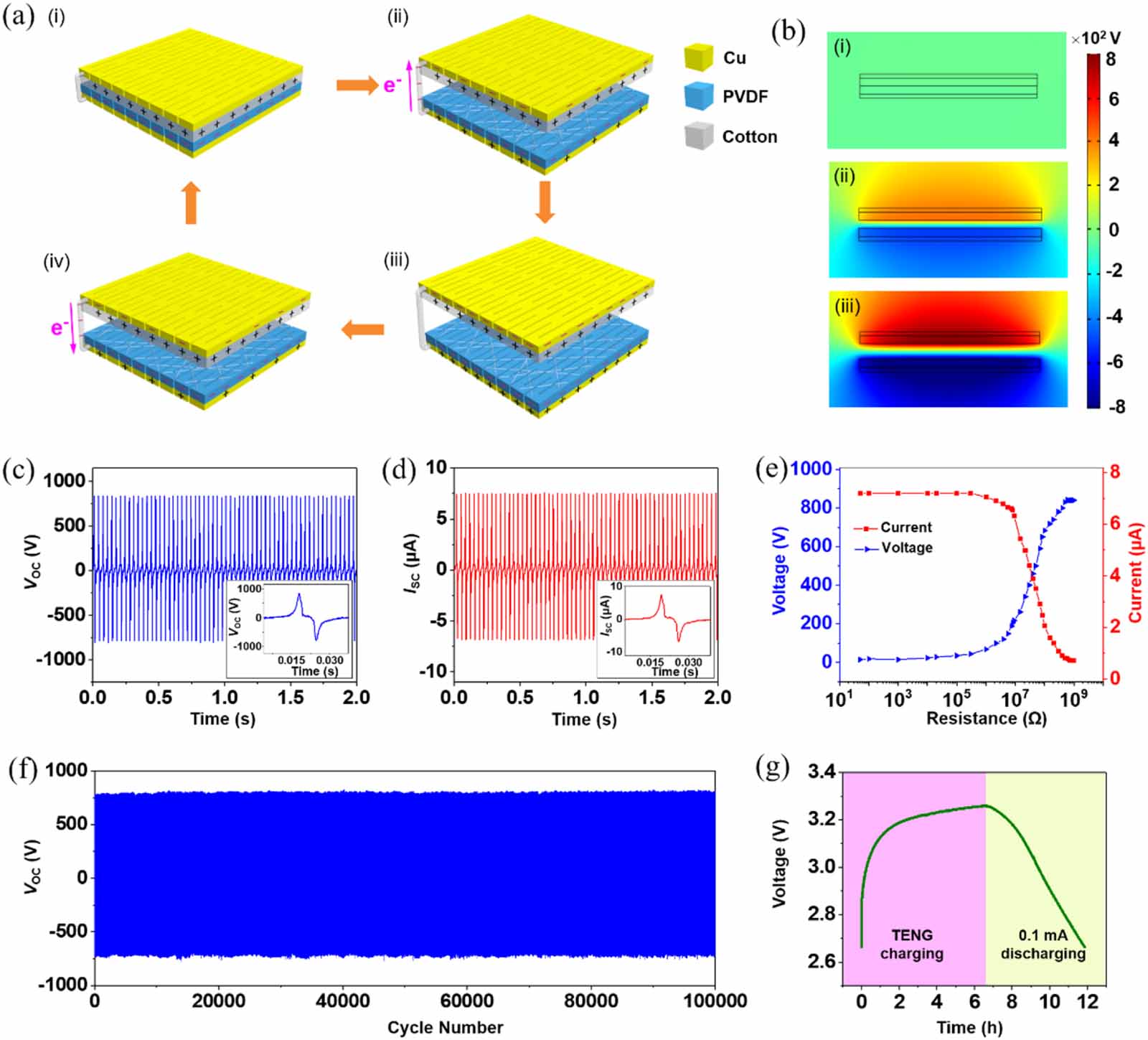
Figure 2. Operating principle and electrical output performance of the K-TENG. (a) Cycle is generally divided into four states. (i) In the beginning, the cotton and the PVDF film are in contact with each other. (ii) Applied external force causes the cotton to separate from the PVDF film by a short distance. (iii) Cotton is completely separated from the PVDF. (iv) Cotton is close to the PVDF film again. (b) COMSOL simulation of potential distribution under the different positions between the two electrodes. Electrical output performance of the K-TENG. (c) VOC of K-TENG at 30 Hz frequency. Inset shows the detailed output voltage in one cycle. (d) ISC of K-TENG at 30 Hz frequency. Inset shows the detailed output current in one cycle. (e) Curve of output voltage and current as the load resistance changes. (f) Output voltage stability test with 100 000 cycles. (g) Voltage curve of a lithium battery charging and discharging.
-
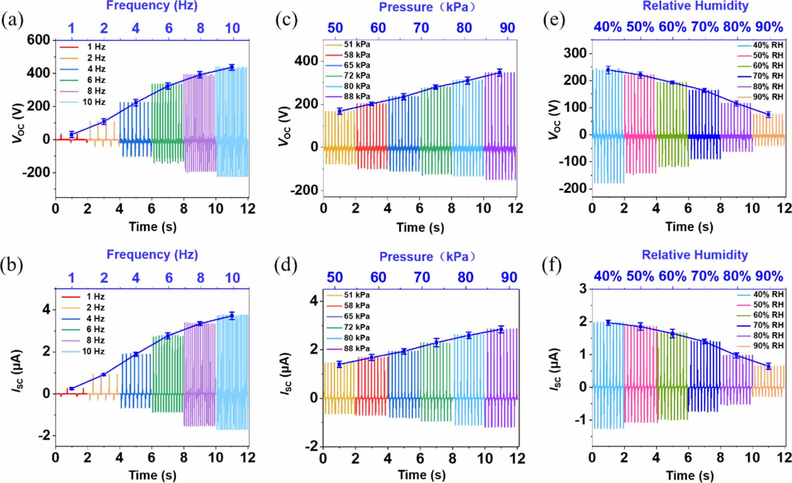
Figure 3. Electrical output performance of the K-TENG under different environmental conditions. (a) VOC and (b) ISC at frequency from 1-10 Hz, electrical output increase with increasing contact frequency. (c) VOC and (d) ISC increase with the increase in contact force in the pressure range of 51-88.5 kPa. (e) VOC and (f) ISC of K-TENG under different atmospheric humidity. Electrical output is inversely correlated with humidity.
-
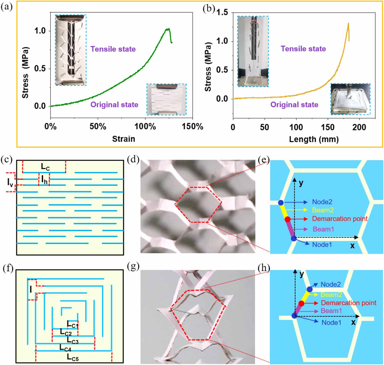
Figure 4. Tensile properties of K-TENG. Stress-strain curves for (a) uniaxial K-TENG and (b) biaxial K-TENG. Schematic diagram of the cutting mode, (c) uniaxial K-TENG and (f) biaxial K-TENG. Optical image of the tensile state of (d) uniaxial K-TENG and (g) biaxial K-TENG. Schematic diagram of the stretched configuration of (e) uniaxial K-TENG and (h) biaxial K-TENG.
-
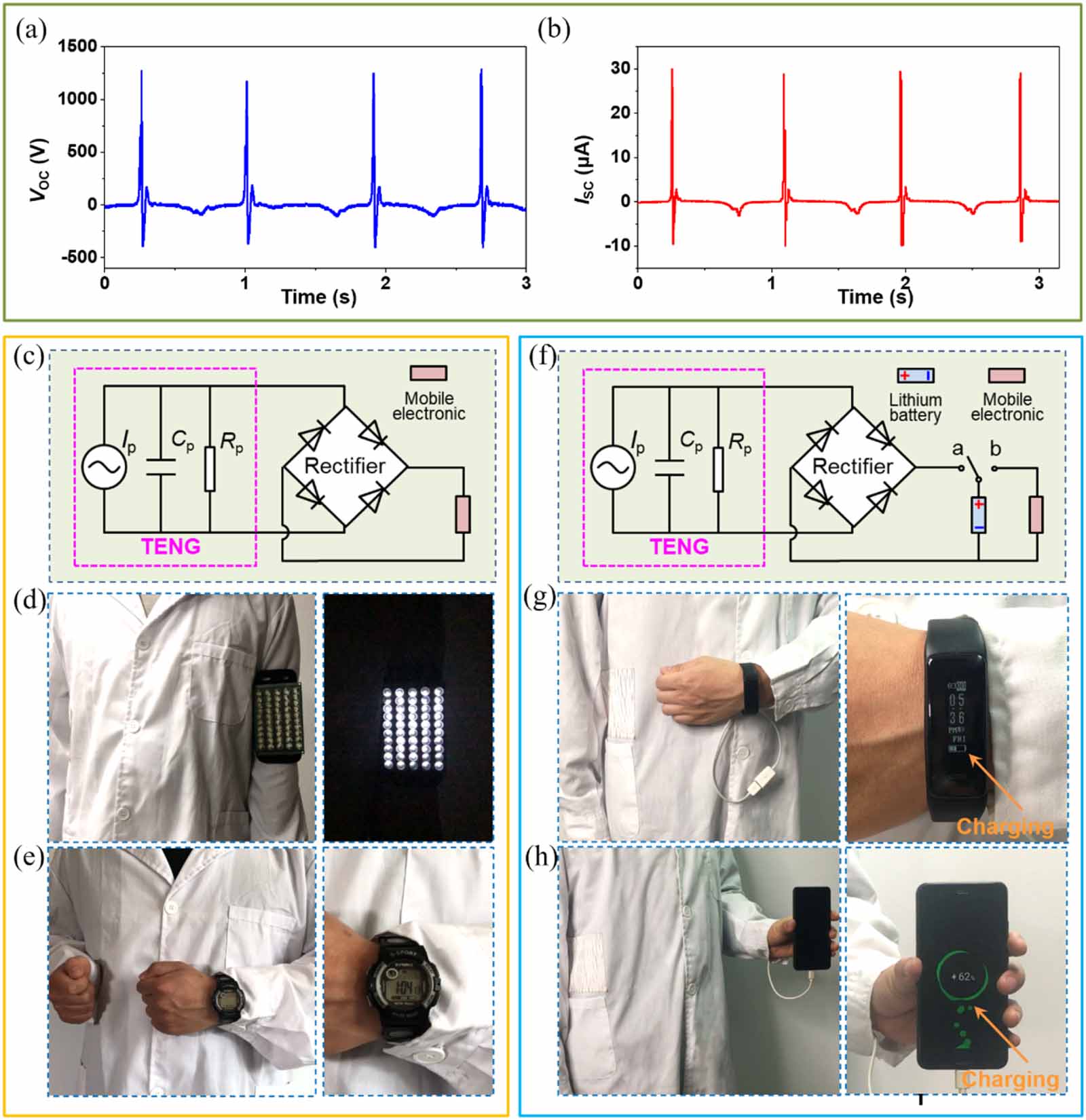
Figure 5. K-TENG on clothes to collect human mechanical energy. (a) VOC and (b) ISC of 13 cm × 10 cm K-TENG integrated into the clothes. (c) Equivalent circuit diagram of a power supply system for direct-drive wearable electronics. (d) Lights up 50 white LEDs and (e) drives a digital watch to work properly and record time accurately. (f) Equivalent electrical circuit diagram of the self-charging power system for charging mobile electronic devices. Self-charging power system charges (g) a smartwatch and (h) a smartphone.
Figure
5 ,Table
0 个