-
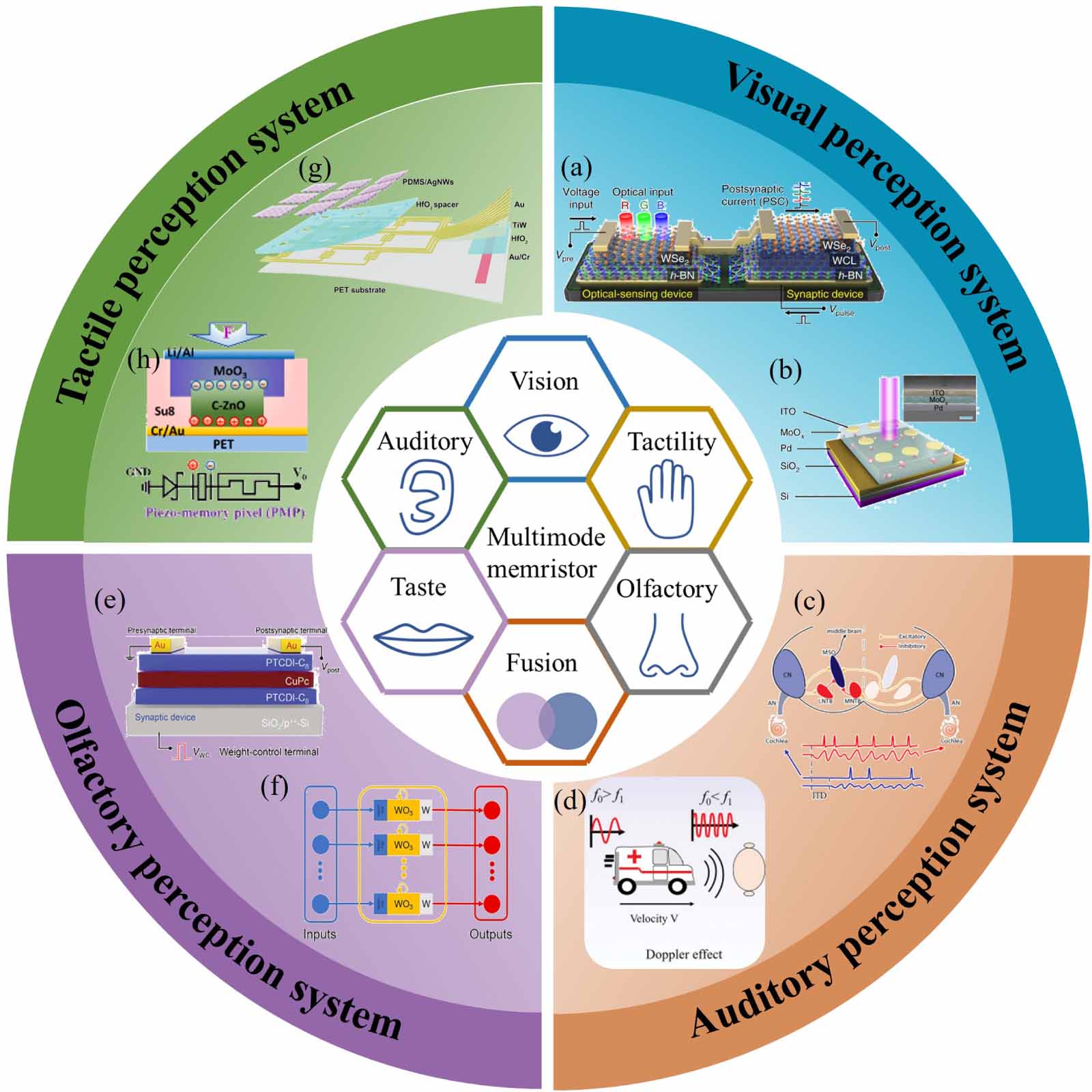
Figure 1. Multimodal perceptual systems based on memristive devices. (a), (b) Artificial visual system with functionalities of color-mixed pattern recognition and image pre-processing. Reproduced from [42].
CC BY 4.0 ; reproduced from [43], with permission from Springer Nature. (c), (d) Auditory motion perception and sound localization demonstrated with memristive device. Reprinted with permission from [44]. Copyright (2018) American Chemical Society; reproduced from [45].CC BY 4.0 . (e), (f) Artificial olfactory system performing gas classification and maintenance of oxygen homeostasis. Reproduced from [46].CC BY 4.0 . [47] John Wiley & Sons. © 2020 WILEYVCH Verlag GmbH & Co. KGaA, Weinheim. (g), (h) Neuromorphic tactile perceptual system based on memristor technology. Reprinted from [48], © 2021 Elsevier Ltd. All rights reserved. [37] John Wiley & Sons. © 2022 WileyVCH GmbH. -
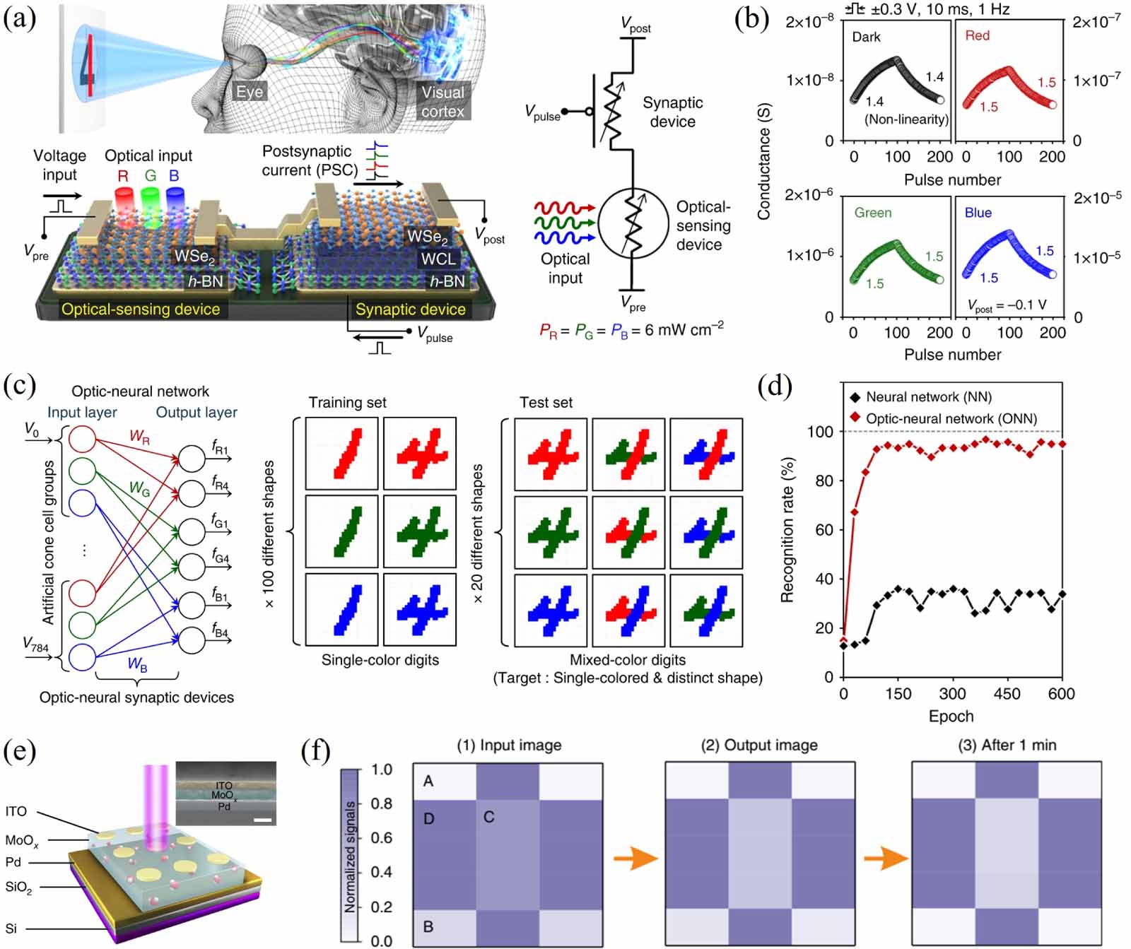
Figure 2. (a) Schematic of human visual system and h-BN/WSe2 optic-neural synaptic device. (b) Long-term potentiation and depression behaviors under different light conditions. (c) Optic-neural network for recognition of color-mixed numeric pattern images. (d) The recognition rate of conventional and optic-neural network. Reproduced from [42].
CC BY 4.0 . (e) Schematic structure of MoOx-based optoelectronic resistive random access memory device. (f) Image contrast enhancement after training processes. Reproduced from [43], with permission from Springer Nature. -
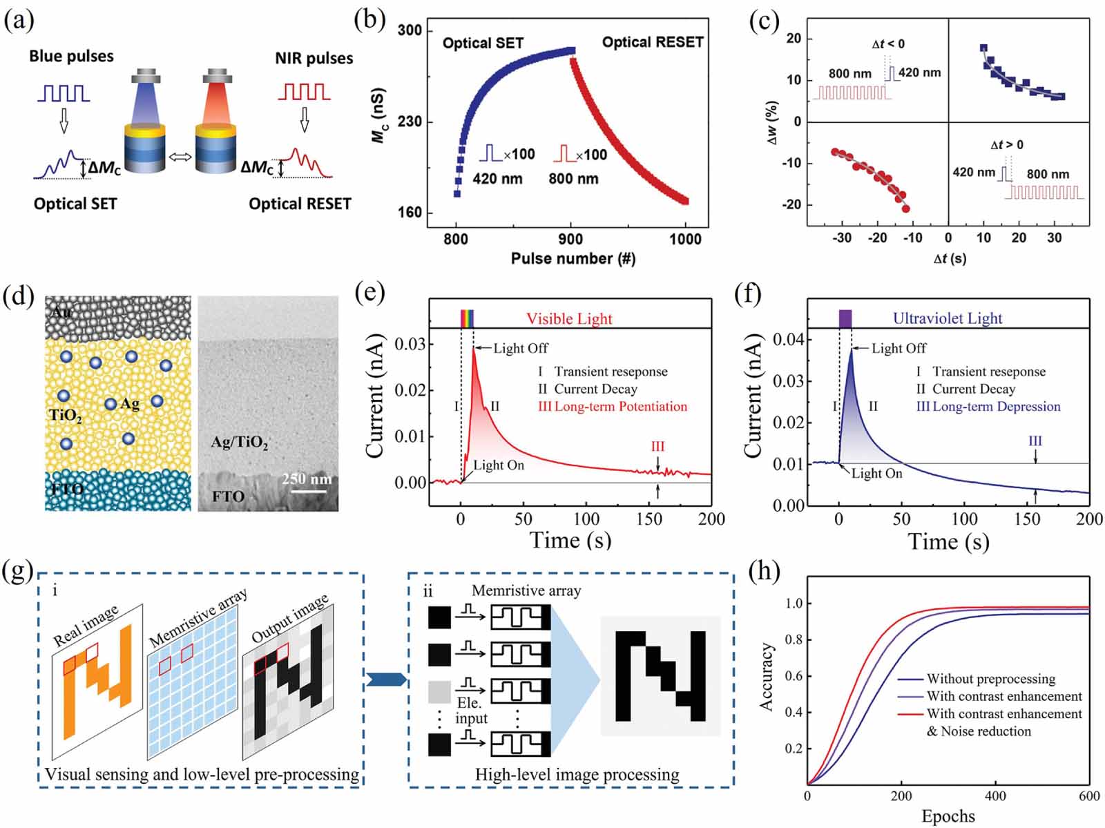
Figure 3. (a) Schematic of all-optically controlled analog memristor. (b) Reversible regulation of device conductance with blue and NIR light pulses. (c) Emulation of synaptic spike-timing-dependent plasticity. Reproduced from [60].
CC BY 4.0 . (d) Device structure and cross-sectional TEM image of Ag-TiO2-based memristor. (e), (f) Synaptic potentiation and depression functions with visible light and ultraviolet spike, respectively. (g) Neuromorphic vision system for integrated visual sensing, image preprocessing, and image processing. (h) Comparison of image recognition rate with and without retina-like pre-processing. Reproduced from [61].CC BY 4.0 . -
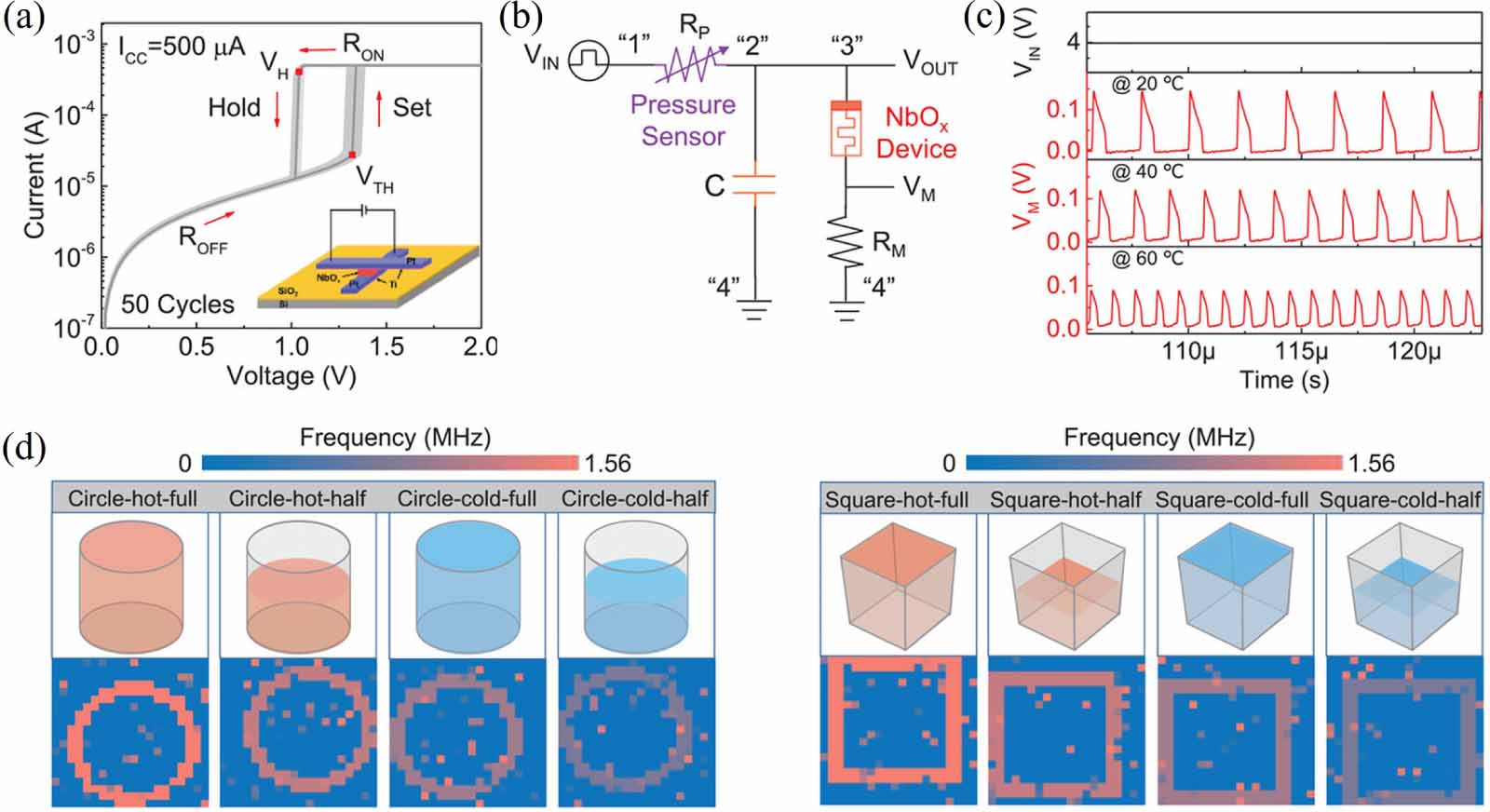
Figure 4. (a) I-V curves of NbOx-based threshold memristor. (b) Circuit diagram of multimodal spiking neuron. (c) Output voltage spikes at temperatures of 20 C, 40 C, and 60 C. (d) Object classification with a simulated multimode-fused spiking neuron array. [68] John Wiley & Sons. © 2022 WileyVCH GmbH.
-
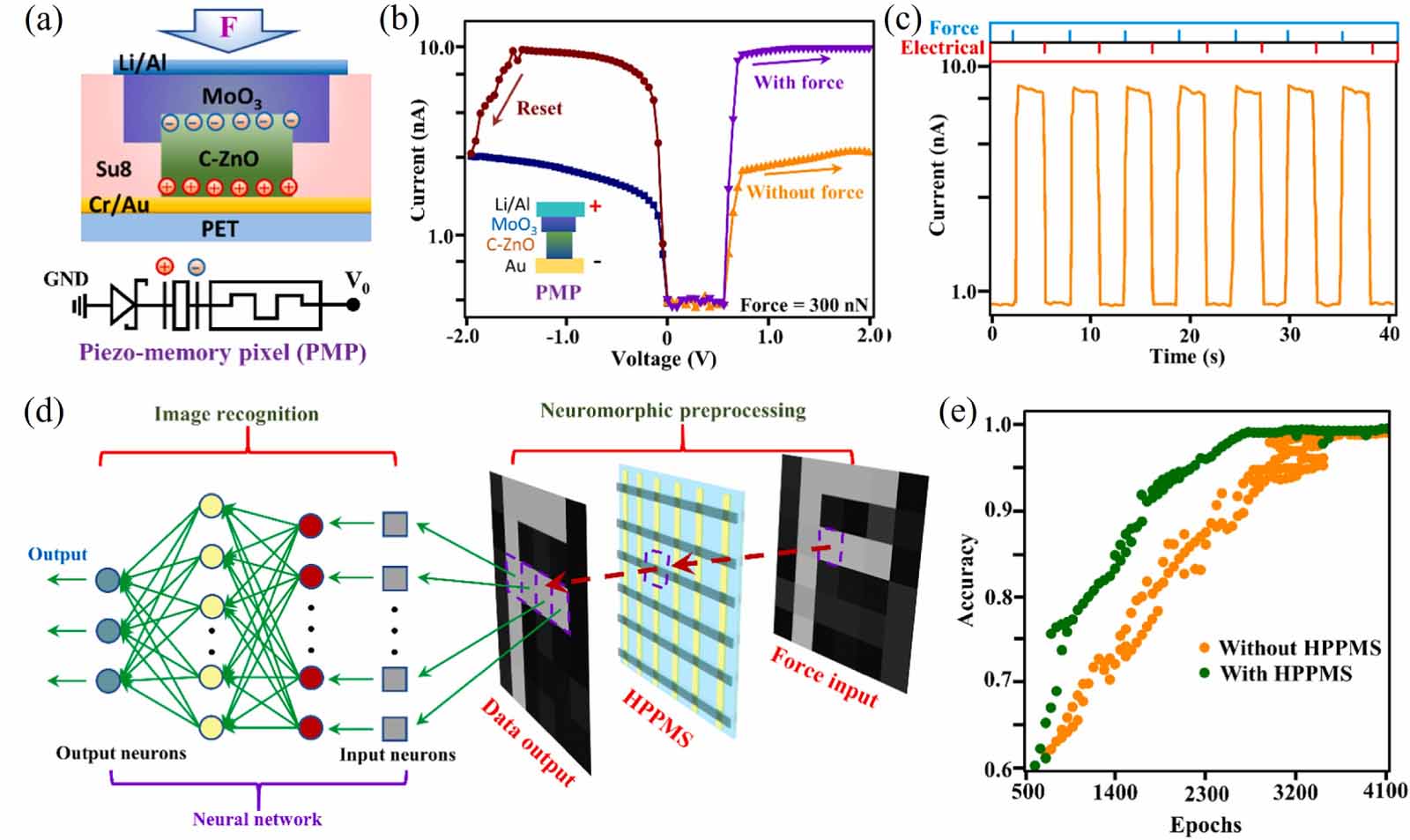
Figure 5. (a) Schematic diagram of piezo-memory pixel. (b) IV characteristics with and without loaded force. (c) Electrical switching performance with force pulse and reset voltage. (d) Image preprocessing and recognition in an artificial neural network based on pressure piezo-memory system. (e) Force-image recognition before and after image preprocessing. Reprinted from [48], © 2021 Elsevier Ltd. All rights reserved.
-
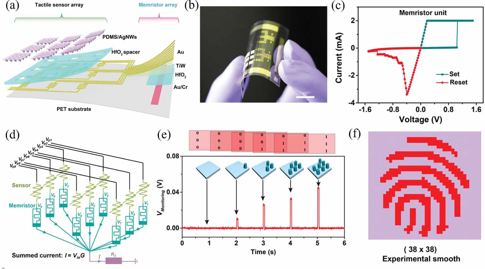
Figure 6. (a) Near-sensor analogue computing system combining pressure sensor array with memristor array. (b) Photograph of artificial skin system. (c) I-V curves of HfOx-based memristor unit. (d) Demonstration of averaging filter and vector-matrix multiplication. (e) Monitoring voltages representing the summed current under different pressure stimuli. (f) Experimental results obtained when applying noise reduction. [37] John Wiley & Sons.© 2022 WileyVCH GmbH.
-
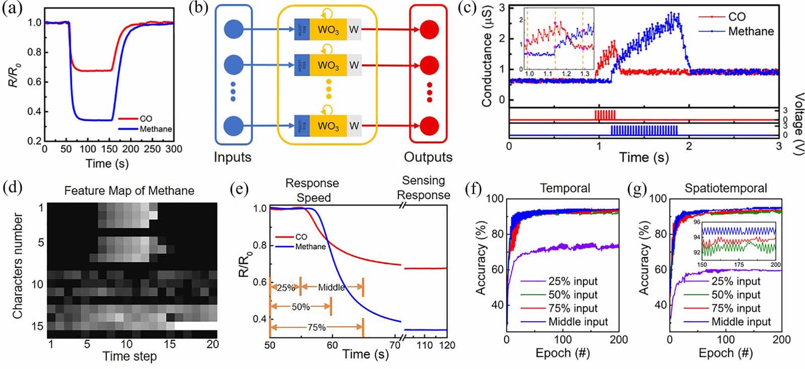
Figure 7. (a) Normalized response and recovery curves of sensor TGS2610 for carbon monoxide and methane. (b) Schematic of reservoir computing system based on memristor. (c) Temporal response of memristive device to pulse trains. (d) Full feature map of methane extracted by the reservoir computing system. (e) Illustration of feature extraction. (f), (g) Classification accuracy with reduced temporal and spatiotemporal dimensions. Reproduced from [46].
CC BY 4.0 . -
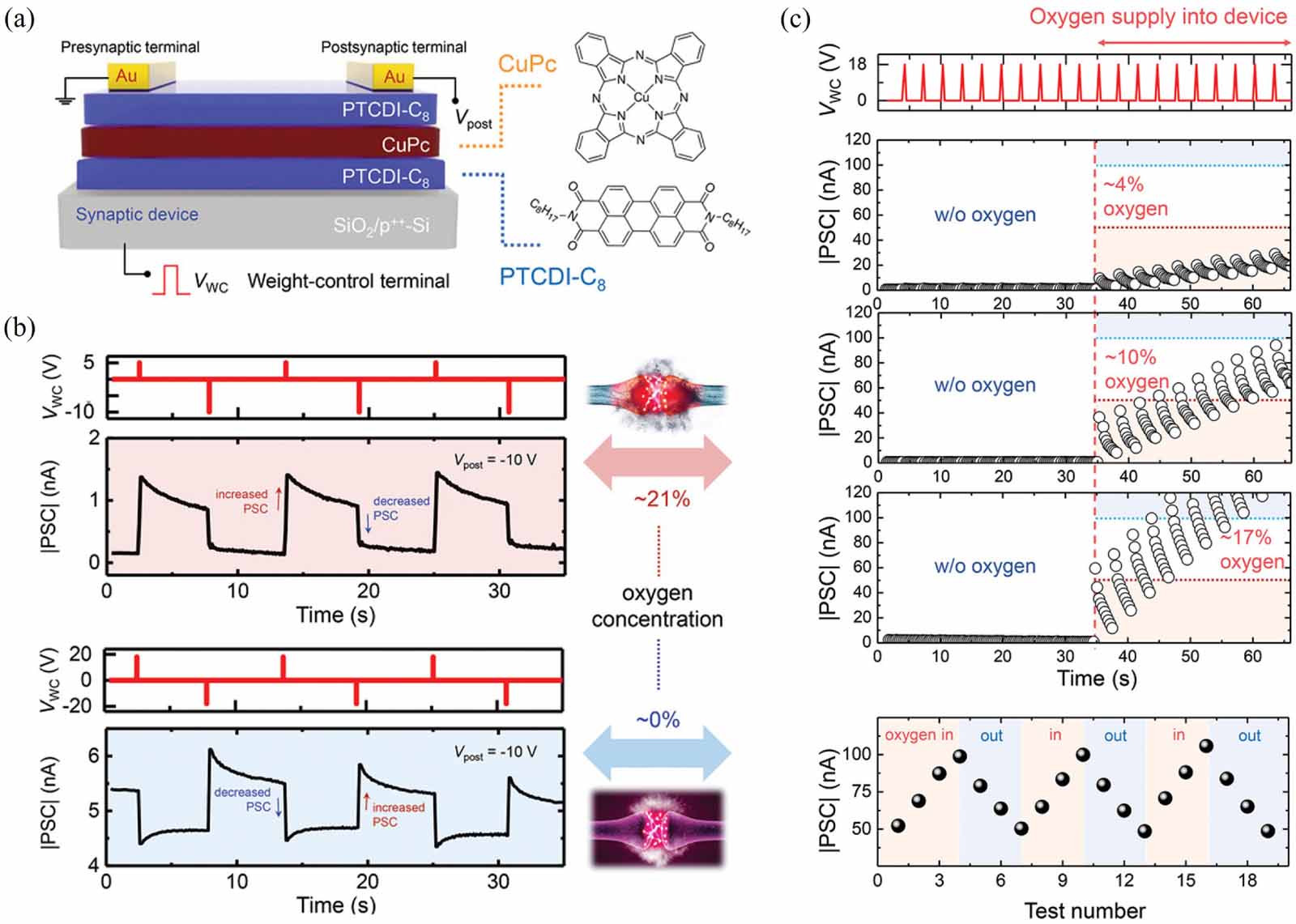
Figure 8. (a) Oxygen-sensitive artificial synaptic device based on PTCDI-C8/CuPc/PTCDI-C8. (b) Postsynaptic current response under the stimulus of positive/negative weight-control voltage pulses at different oxygen concentrations. (c) Operation of negative feedback system for maintaining oxygen homeostasis. [47] John Wiley & Sons.© 2020 WILEYVCH Verlag GmbH & Co. KGaA, Weinheim.
-
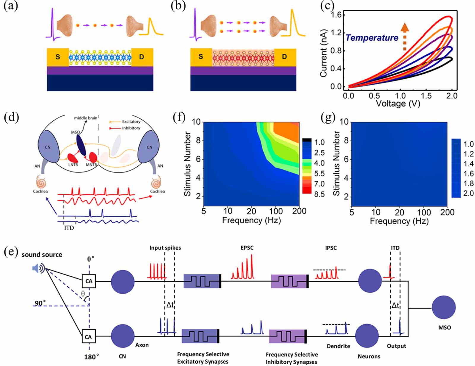
Figure 9. (a), (b) Monolayer MoS2 based artificial synaptic device without/with Joule heating. (c) Conductance facilitation driven by Joule heating in voltage sweep mode. (d) Schematic diagram of sound localization with interaural time difference and interaural level difference. (e) Working mechanism of synaptic computation for sound localization. (f), (g) Frequency and stimulus number-dependent output with/without synaptic computation. Reprinted with permission from [44]. Copyright (2018) American Chemical Society.
-
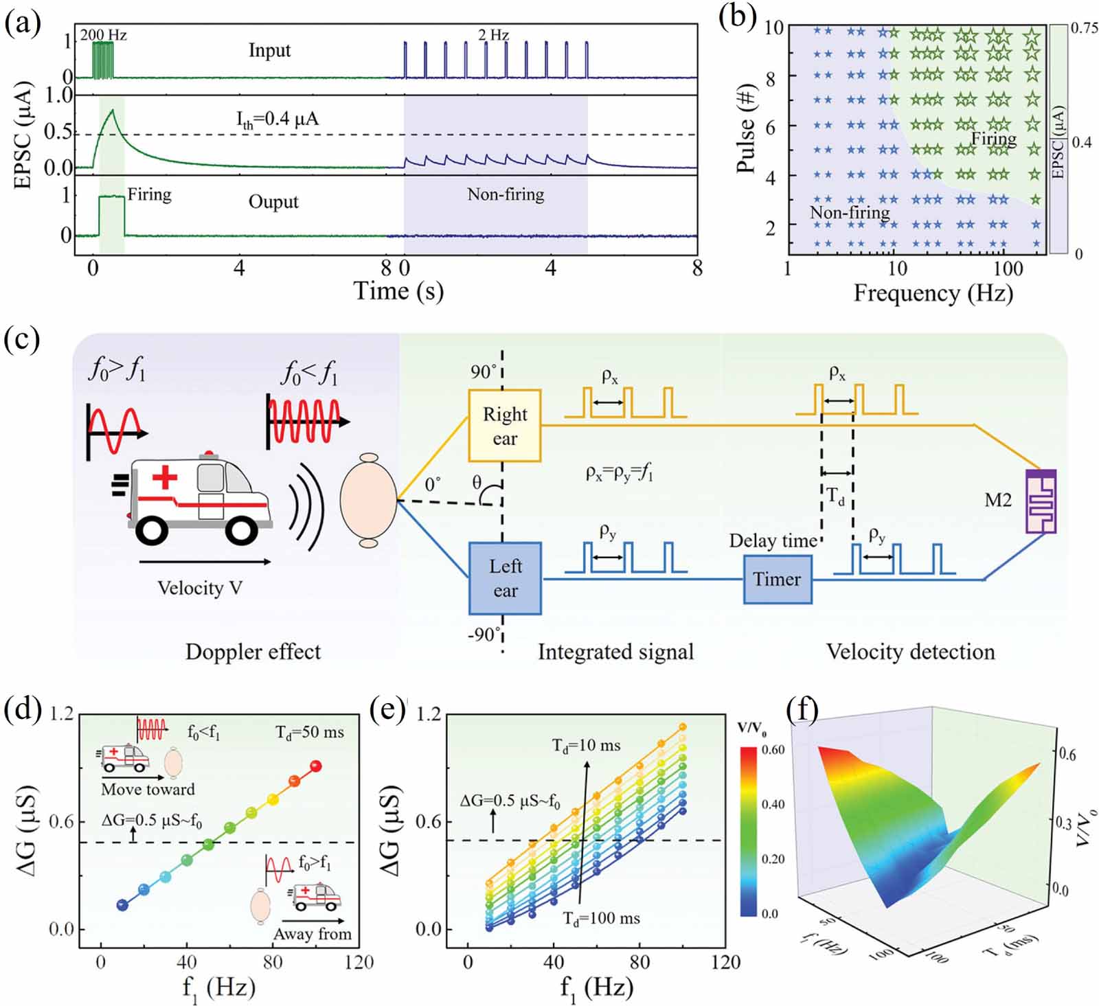
Figure 10. (a) High-pass filtering and firing during stimulations. (b) Experimental conditions for firing and non-firing operations. (c) Circuit design of Doppler velocimeter. (d) Conductance change as a function of spike frequency. (e) Dependence of spike frequency and conductance change on different delay times. (f) Experimental results of relative velocity for Doppler velocimeter. Reproduced from [45].
CC BY 4.0 . -
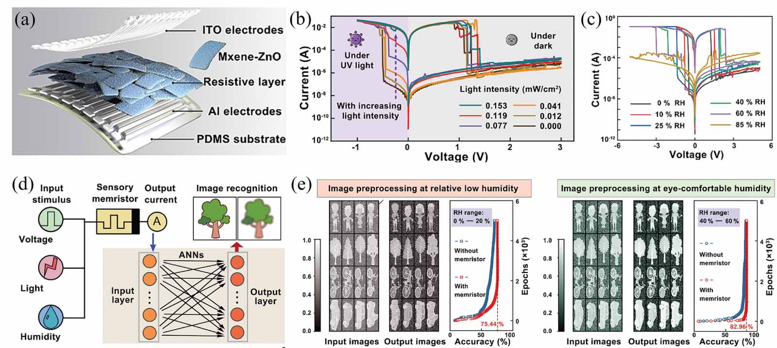
Figure 11. (a) Schematic illustration of flexible MXene-ZnO based memristor array. (b)-(c) I-V curves under various light irradiance and RH condition. (d) Schematic illustration of in-sensor processing with MXene-ZnO memristor. (e) Recognition results at low humidity and eye-comfortable humidity condition. [81] John Wiley & Sons. © 2021 WileyVCH GmbH.
Figure
11 ,Table
0 个