-
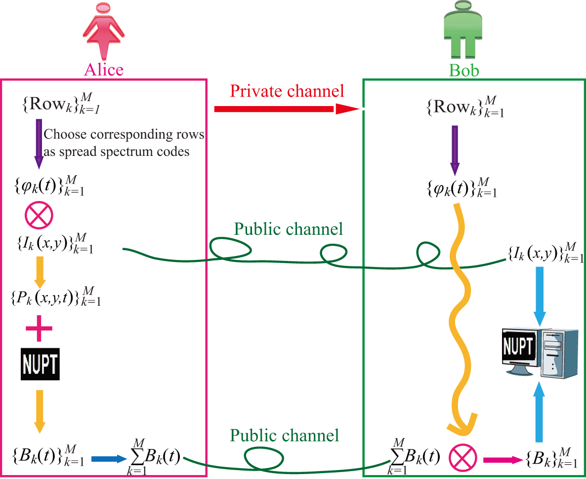
Figure 1. Schematic diagram of the SSGI-OE scheme.
-
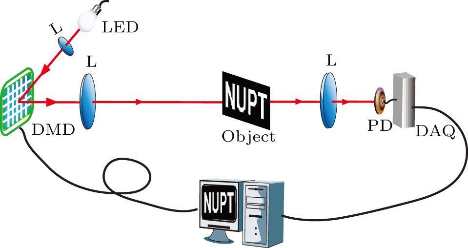
Figure 2. The experimental setup for the proposed SSGI-OE scheme system. LED: light emitting diode. DMD: digital mirror device. L: lens. PD: photodetector. DAQ: data acquisition card.
-
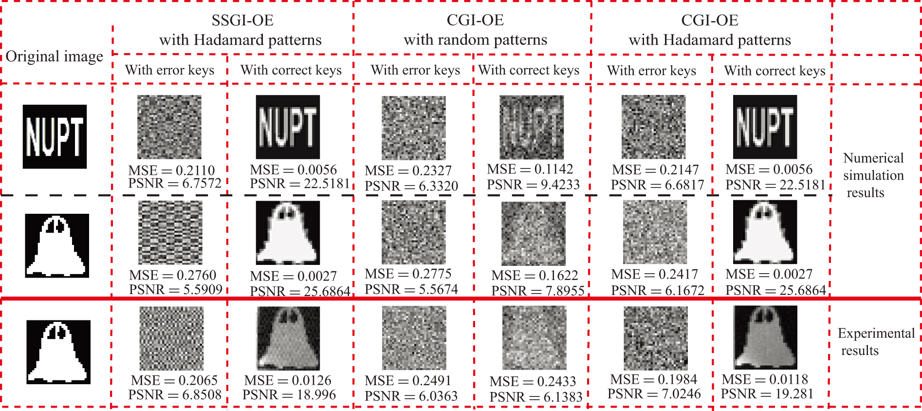
Figure 3. Comparison of the numerical simulations and experimental results by SSGI-OE and CGI-OE with Hadamard speckle patterns and random speckle patterns.
-
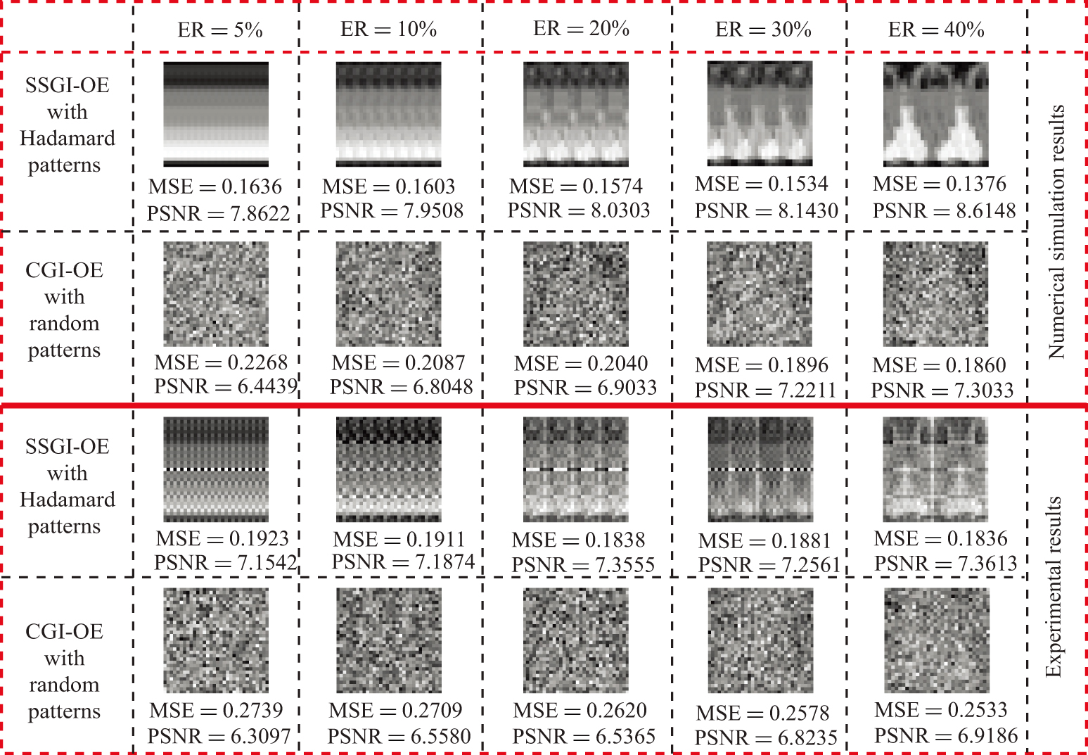
Figure 4. Comparison of simulated and experimental results under different eavesdropping ratios.
-
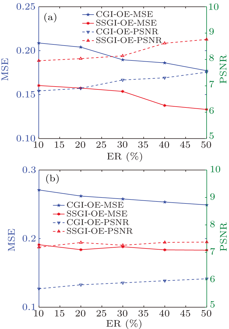
Figure 5. The MSE and PSNR of the recovered images against the eavesdropping ratio: (a) the simulated results, (b) the experimental results.
-
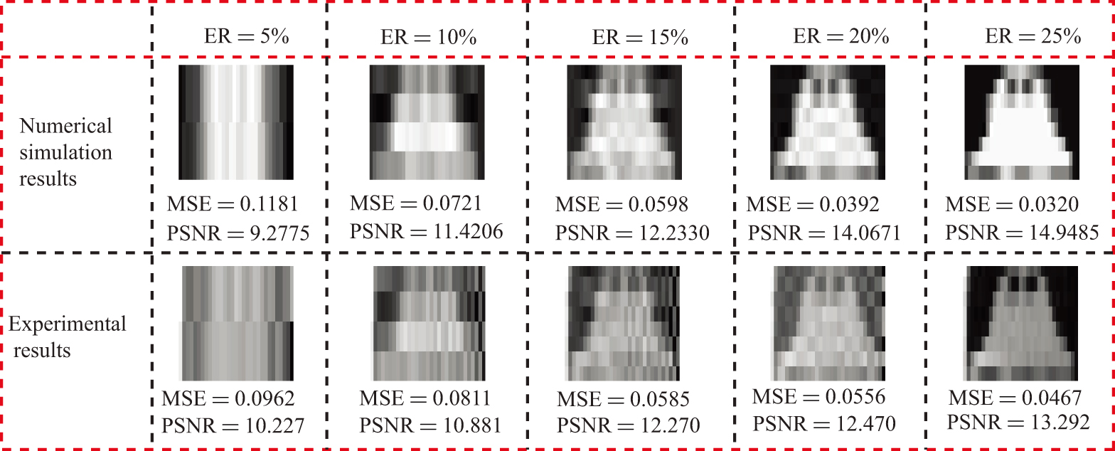
Figure 6. Simulated and experimental results by the proposed SSGI-OE scheme under different eavesdropping ratios at the extreme circumstance.
Figure
6 ,Table
1 个