Figure 8 ,Table 5
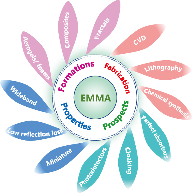
    • Figure 1.  Schematic of the introduction of EMMA, including features from design to application.

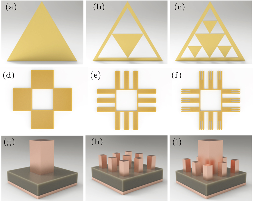
    • Figure 2.  Schematic diagram of the standard Sierpinski fractal of (a) first-order, (b) second-order, (c) third-order.

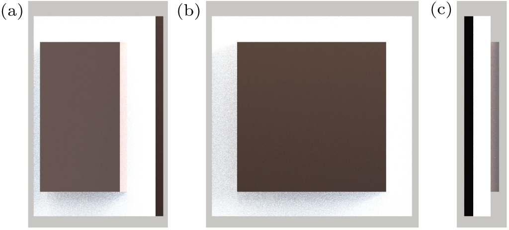
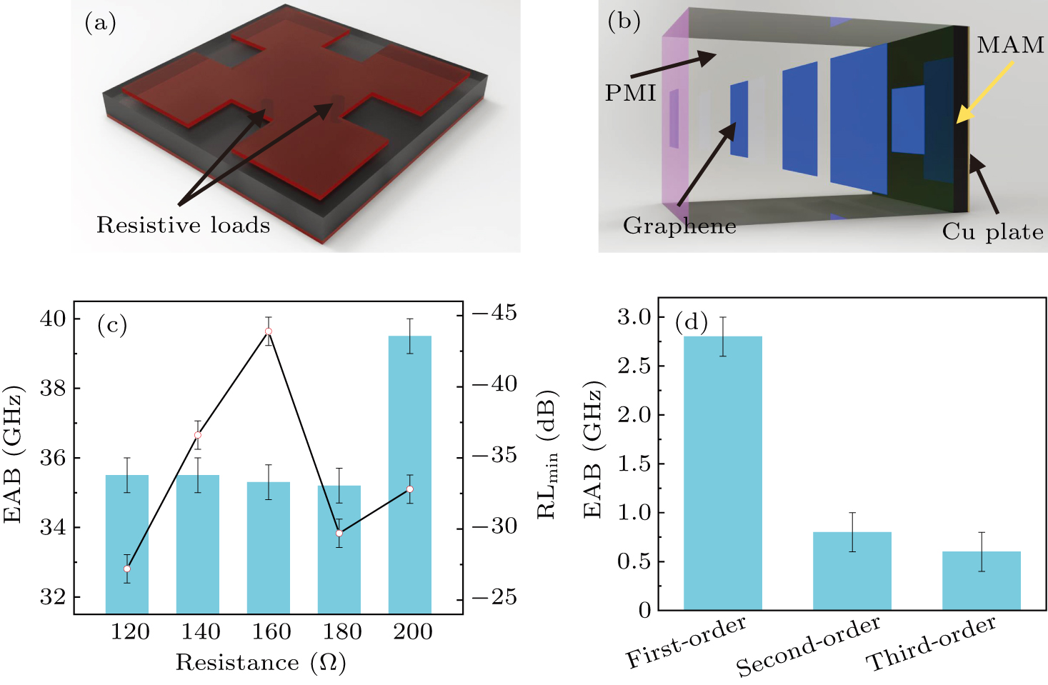
    • Figure 3.  (a) Perspective, (b) front view, (c) end view of the proposed absorber.

    • Figure 4.  Schematic diagram of first-order, second-order and third-order absorbers, (a)–(c) in Ref. [13], (d)–(f) in Ref. [60], (g)–(i) in Ref. [70].

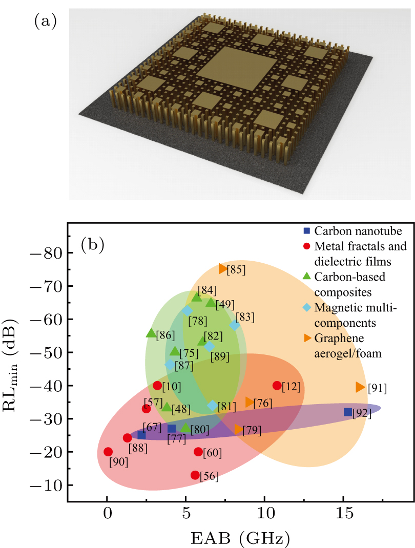
    • Figure 5.  (a) The perspective of gold/graphene plasma fractal absorber in Ref. [9]. (b) Electromagnetic absorption performance of EMMAs of different materials.

    • Figure 6.  (a) Schematic diagram of the preparation process of rGO/PI foam in Ref. [54]. (b) Schematic diagram of Yolk-shell-structure Co–C/void/Co9S8 composites in Ref. [38].

    • Figure 7.  Schematic diagram of metamaterial absorber in (a) Ref. [90], (b) Ref. [55]. (c) Variation of RL and EAB with resistance in Ref. [55]. (d) Effect of different fractal levels on EAB in Ref. [60].

    • Figure 8.  (a) Effect of annealing temperature on EAB and RL in Ref. [105]. The frequencies corresponding to the low-frequency absorption peaks of absorbers of different thicknesses (b) in Ref. [55], (c) in Ref. [52].