-
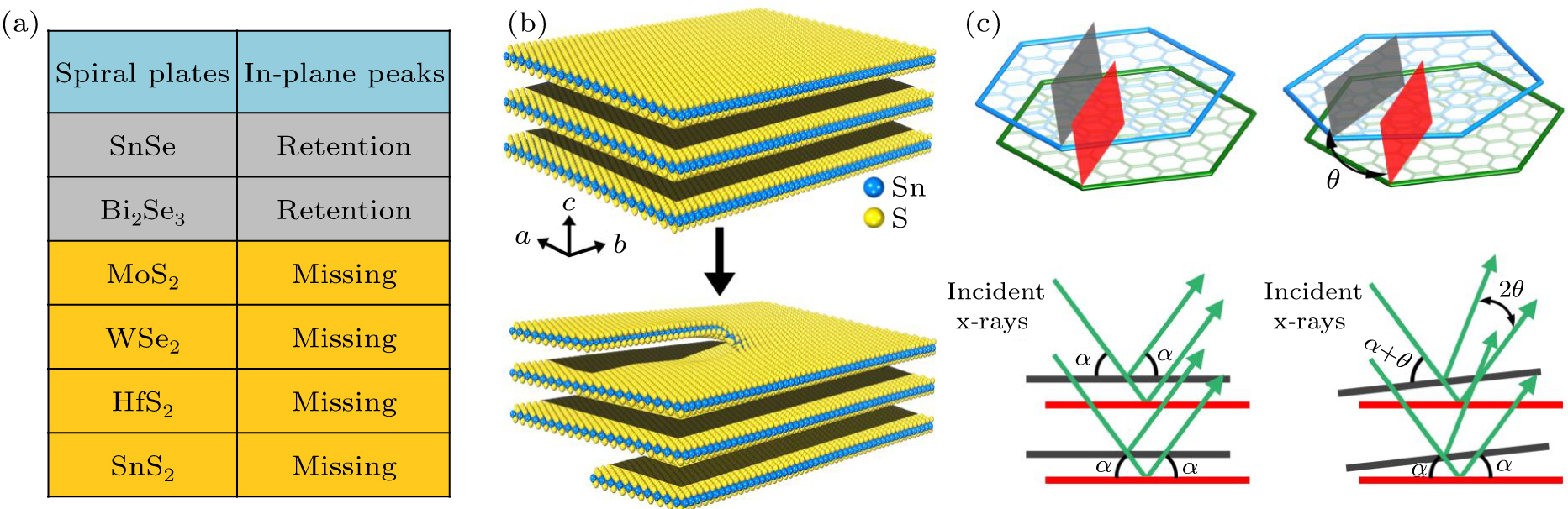
Figure 1. Explanation of the formation of MSLs in the spiral plates with a small twist angle. (a) A series of 2D spiral plates recently driven by screw dislocations under low supersaturation condition. In addition, the retention or missing of in-plane peaks is also shown. (b) Schematic representation of the incorporation of screw dislocation from layer-by-layer structure to spiral structure. (c) Schematic representation of XRD of 2D plates without or with a small twist angle.
-
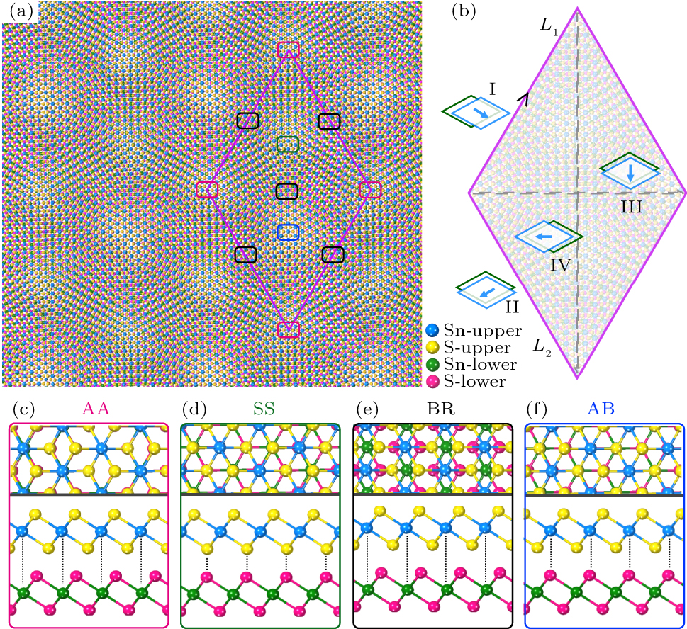
Figure 2. Atomic structures of SnS2 spiral bilayer MSL. (a) Perpendicular view of the topological SnS2 spiral bilayer structure with a twist angle of 3.1°, forming a MSL with the periodicity L = 6.75 nm. (b) Four typical paths of the SnS2 MSL shown in the pink rhombus in (a). (c)–(f) Top and side views of the bilayer structures at four high symmetry regions marked in (a), namely, AA, SS, BR, and AB structures, which are indicated by red, green, black, and blue squares, respectively.
-
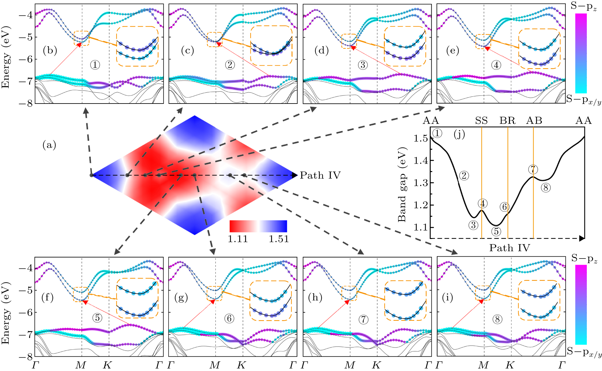
Figure 3. Electronic properties of SnS2 spiral bilayer MSL. (a) Spatially resolved band gaps of SnS2 MSL. (b)–(i) Calculated band structures of crucial stacking patterns along path IV. The band structures have been projected onto atomic orbitals with the weight of the out-of-plane S-pz and the in-plane S-px/y orbitals. (j) Evolution of band gaps for the local stacking structures along path IV.
-
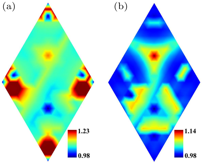
Figure 4. Optical activity of SnS2 spiral bilayer MSL. Spatially resolved overlap integrals of (a) indirect band gap transition and (b) direct band gap transition of SnS2 MSL. The value of AA structure is normalized for comparison.
Figure
4 ,Table
0 个