-
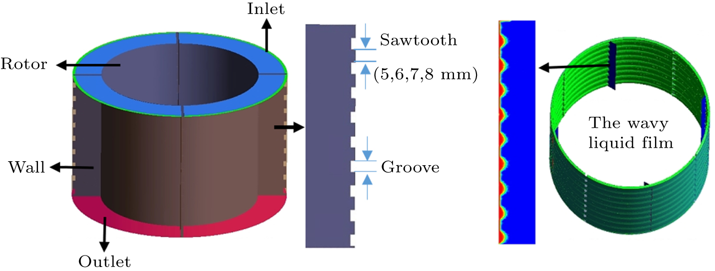
Figure 1. Comprehensive schematic and liquid film representation of ATFE.
-
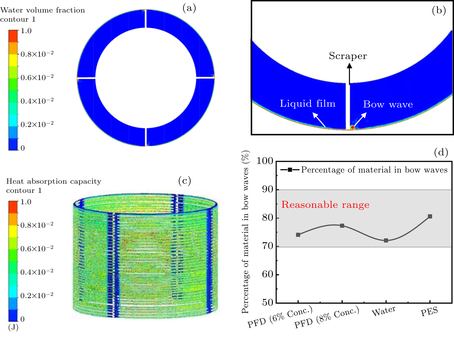
Figure 2. (a) Diagrammatic representation of ATFE’s flow field, (b) expanded depiction of the region adjacent to the scraper, (c) diagram of heat absorption distribution of material, (d) proportion of material in the bow wave.
-
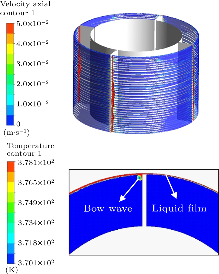
Figure 3. Characteristics of material within ATFE: (a) spread of material speed and (b) temperature distribution in material around a circular area.
-
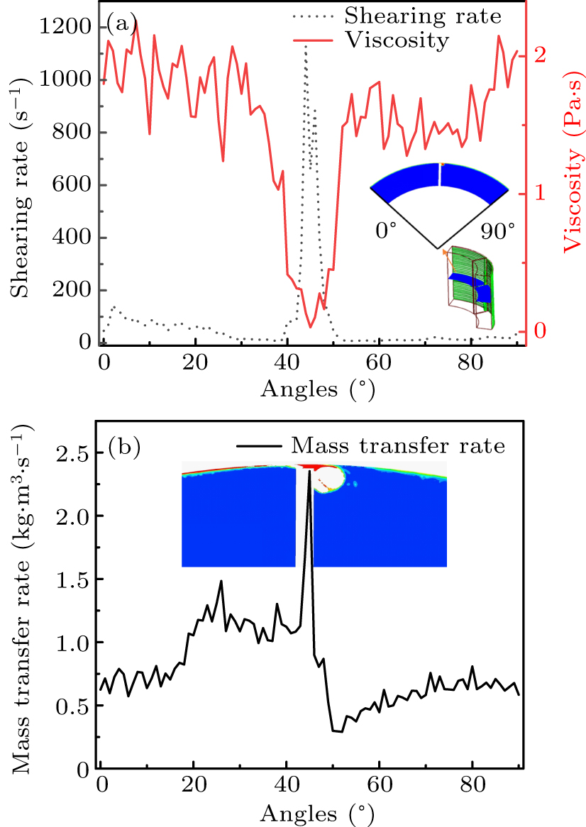
Figure 4. Thinning due to shearing in ATFE: (a) distribution of shear rate and viscosity around circumference, and (b) spread of mass transfer rate of liquid film across circumferential cross-section.
-
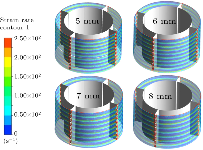
Figure 5. Shear rate distributions of liquid film with different scraper structures.
-
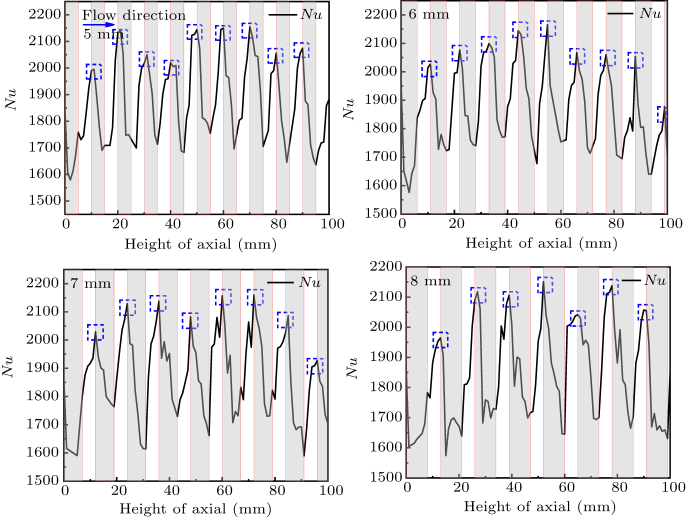
Figure 6. Nusselt number distributions of liquid film along axial height with different scraper structures.
-
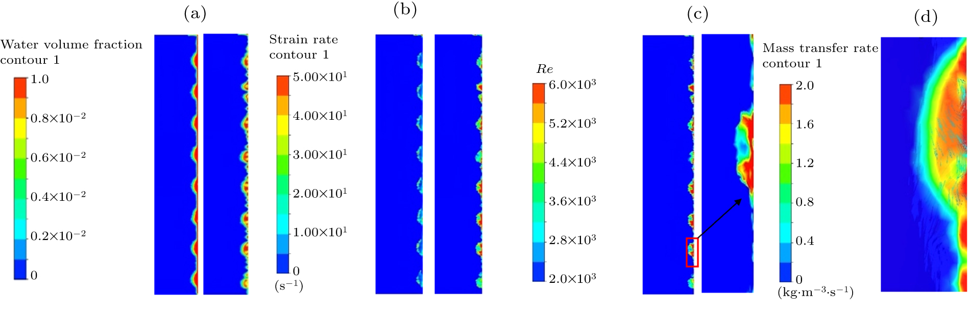
Figure 7. State analyses of liquid film’s pre and post-evaporation: (a) fracture of liquid film, (b) conditions of shear in liquid films, (c) flow condition of liquid film, (d) mass transfer in the liquid film within the groove.
-
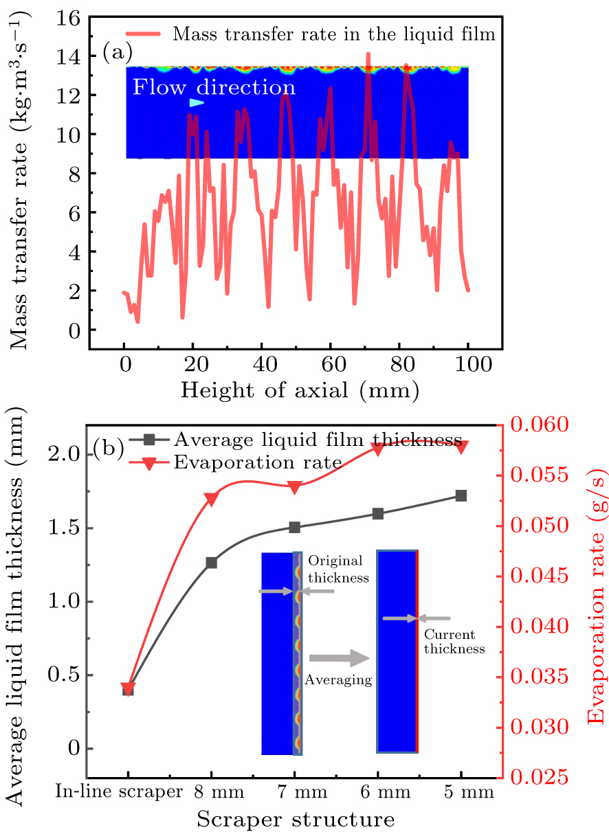
Figure 8. Influence of thinning area of liquid film on the evaporation capability of the ATFE: (a) influence of the thinning zone on liquid film’s mass transfer speed and (b) relation between mean thickness of liquid film and rate of evaporation.
-
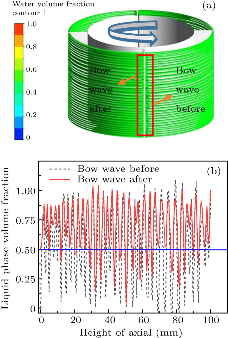
Figure 9. Distribution of liquid films before and after the bow wave phenomenon: (a) allocation of liquid film across the evaporation wall, and (b) fracturing of the liquid film before and after the bow wave.
-
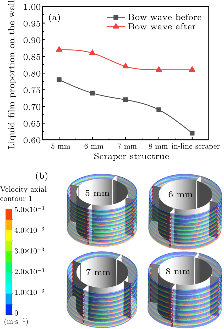
Figure 10. Examining liquid film proportion on the wall: (a) liquid film proportion on the wall under diverse liquid film shapes, (b) axial speed distribution of each wavy liquid film in sawtooth scraper.
-
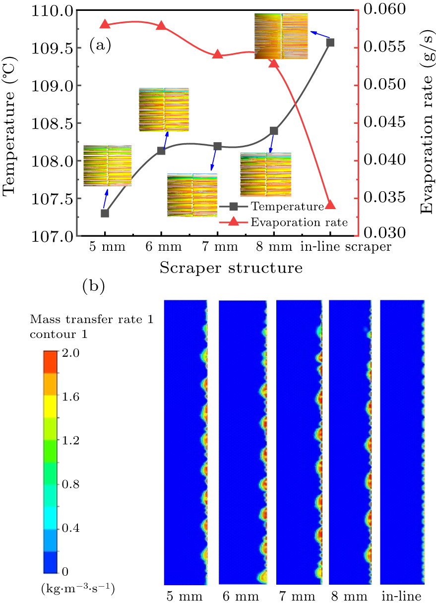
Figure 11. (a) Variations in temperature and rate at which liquid films evaporates and (b) mass transfer rates in various shapes of the liquid film.
Figure
11 ,Table
2 个