
 首页
首页 登录
登录 注册
注册


 下载:
下载:
-
罗茨泵作为一种重要的真空设备,通过泵腔内一对叶形转子反向的非接触同步旋转,实现介质的抽吸与推排功能,动力则由同轴串联的外啮合齿轮副提供[1],广泛应用于真空、石油化工等行业领域[2]。其中,转子的共轭轮廓是形成输送介质的容积限界,直接决定了泵的流量特性[3],能用于共轭轮廓的曲线类型,既有常规的渐开线[4]、圆弧[5]和摆线[6],也有非常规的圆锥曲线[7-9]、直线[10]和弦线[11],还有创新的NURBS曲线和组合曲线等[12-14]。尤其转子的形状系数直接影响着泵的容积效率,形状系数越大,容积效率越高[15],轻量化效果越好[16]。因此,在泵设计尤其轻量化设计时,有必要采用最大化的形状系数[17],这自然就涉及到共轭轮廓的极限判断及其最大形状系数的确定问题。目前,以形状系数为变量,藉由共轭轮廓存在零曲率半径的条件和欧拉-萨伐里共轭方程[18],从由节圆外的已知轮廓求节圆内的待定轮廓[19-20](简称为由外定内)和节圆内的已知轮廓求节圆外的待定轮廓[21-22](简称为由内定外)的两方面,展开了不同曲线类型下的极限研究,这种方法简称为零曲率半径法,但也面临着曲率半径中共轭轮廓二阶导数的繁琐计算或根本无二阶导数,所求得的最大形状系数有些为非解析的数值解[7-9]导致应用性、通用性不强的问题。加之转子形状系数是轮廓设计的(结)“果”,什么样的“因”直接影响着这个“果”,鲜见相关文献报道。有鉴于此,拟就形状系数最大化(“果”)的转子设计,提出一种啮合角最小化(“因”)的通用方法,以克服现有零曲率半径法应用上的局限性。
-
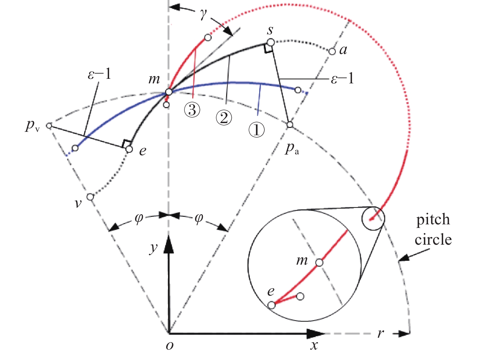
以3叶渐开线转子为例,三种不同的啮合角55.04°、40.19°、17.27°所对应的渐开线轮廓①、②、③,如图1所示。其中,γ为啮合角,0≤γ≤90°,o为转子中心,a、m、v为转子半叶轮廓的顶端点、节点、谷端点,pa、pv为节圆与oa、ov的交点,r为节圆半径,as为以pa为圆心的顶过渡圆弧;sm、me为节圆外、内的共轭轮廓,中心角均为φ=0.5π/N为端点相位角,N为转子叶数,ms和me具有同一转子上的双对称构造关系[23],彼此间可相互确定,由此出现了和由外ms定内me和由内me定外ms的两种构造方法,其中,由外定内的应用最为普遍,由内定外的应用相对较少;ev为以pv为圆心的谷部过渡圆弧;对应于三种不同啮合角的形状系数ε=1.3、1.4、1.5。其中,形状系数的定义为
由此可见,γ越小,ε越大,说明γ与ε具有直接的因果关系。但γ=17.27°时端点e处出现了干涉现象,原因在于该处出现了曲率半径<0的情况。因此,从“因”的角度则要求γ≥最小啮合角γmin,从“果”的角度则要求ε≤最大形状系数εmax。
干涉现象导致了端点e的横坐标左右、纵坐标上下的异向变动,则异向变动和异向不变动之间的临界条件为横坐标和纵坐标的导数均为零。由此推断出零曲率半径等价于其横纵坐标的零导数,由于任何共轭轮廓曲线的导数均存在,所以横纵坐标的零导数方法(简称为零坐标导数法)能有效避免现有零曲率半径法的应用问题。
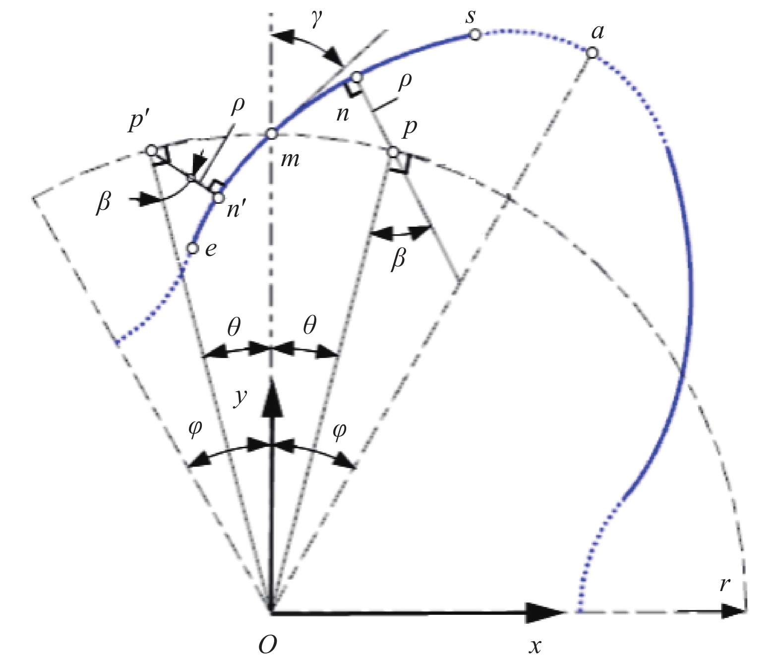
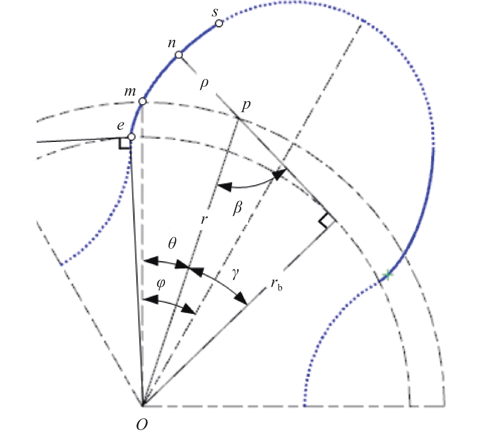
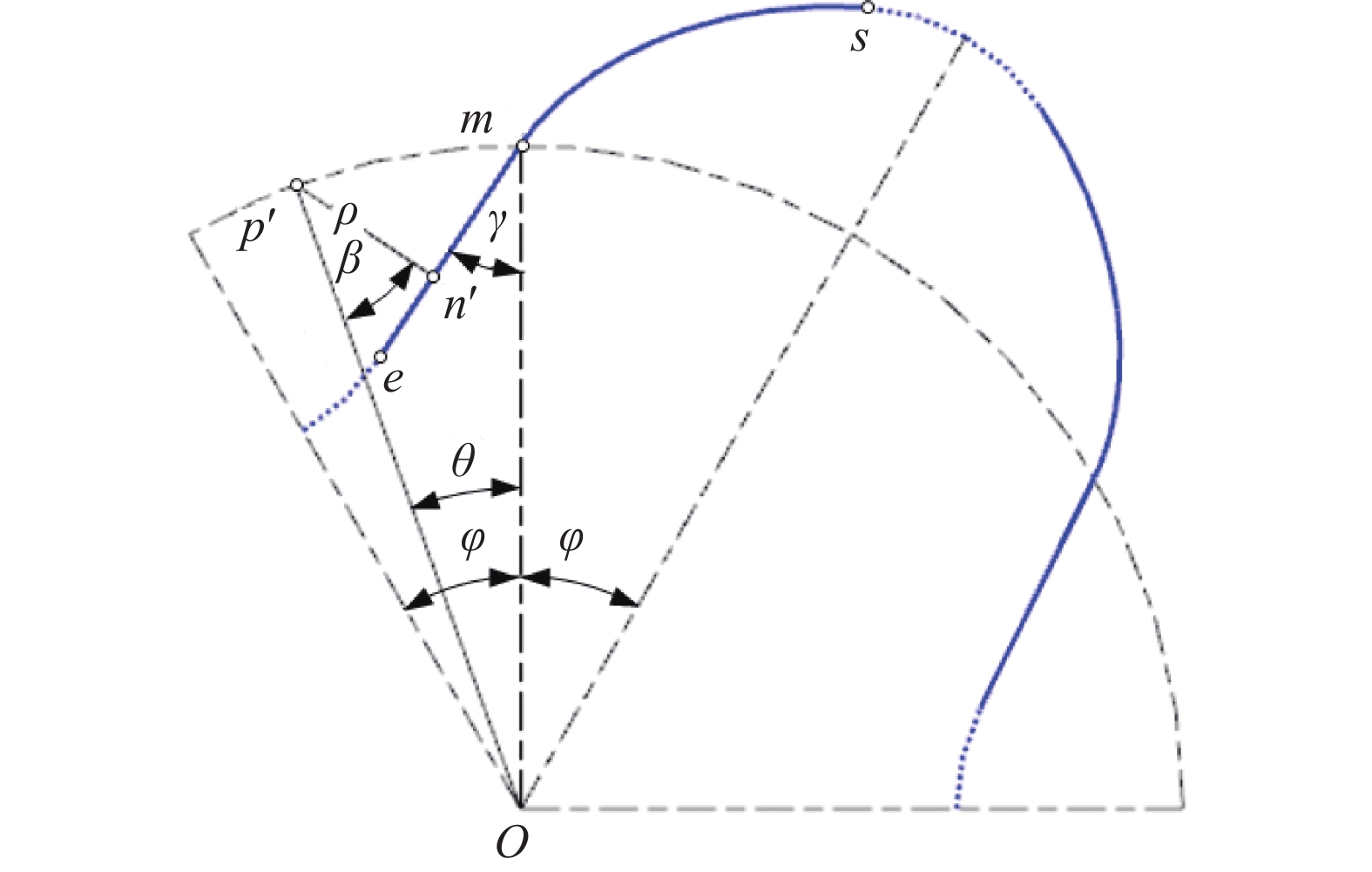
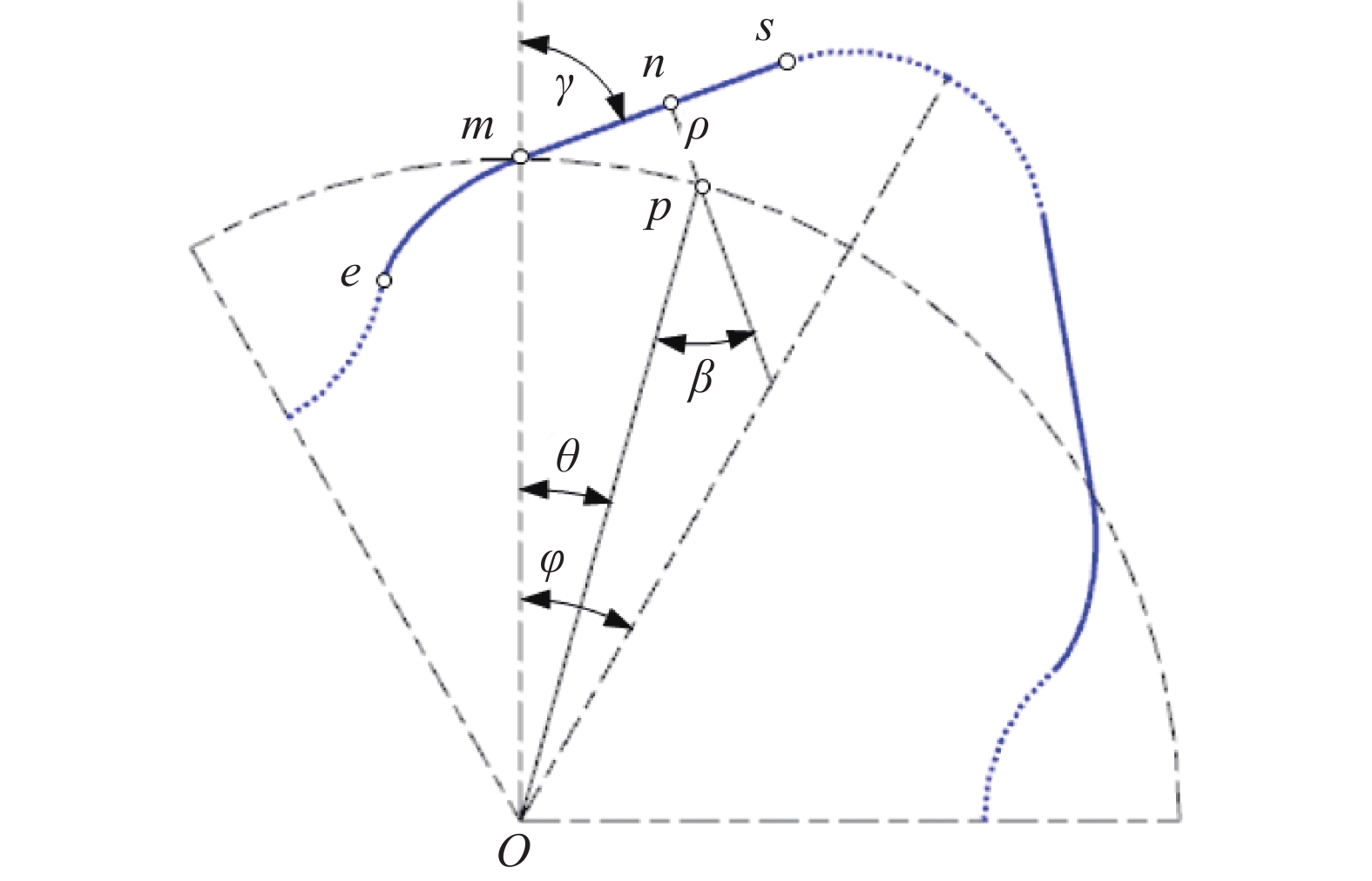
ms和me间的构造关系,如图2所示。其中,n/p、n'/p'为ms/me上的啮合点/瞬心;当op、op'与om的夹角均为相位角θ时,则n和n'处的传动角均为β(θ,γ),0≤β≤90°,pn和p'n'的长度均为ρ(θ,γ)[23]。由此得因果关系式为
即γ 透过β(0,γ),β(0,γ)透过rsinβ=dρ/dθ[18],ρ(θ,γ)透过其端点相位角的ρ(φ,γ)实现对ε(γ)的大小控制。其中,ε(γ)=ε(γmin)=εmax的形状系数最大化等价于β(θ,γ)=β(θ*,γmin)=βmax的传动角最大化,传动角最大化又等价于γ=γmin的啮合角最小化,即形状系数的 最大化最终等价于啮合角的最小化,εmax为由端点位置处形状系数ε的最大值,βmax为[0,φ]内最大传动角,θ*为[0,φ]内βmax所在位置处的相位角,γmin为节点位置处啮合角γ的最小值。
由此建立出将端点处的形状系数ε(γ)及其最大化ε(γmin),通过共轭轮廓共轭区间[0,φ]内的传动角β及其最大化β(θ*,γmin),最终落实在节点处啮合角γ及其最小化γmin上的内在因果关系。
在图2坐标系xoy下,由p、p'的坐标(rsinθ,rcosθ)、(−rsinθ,rcosθ),得sm、me的坐标方程
和
-
在由外定内的轮廓构造中,零曲率半径发生在节圆内共轭轮廓me上。则由式(4),得其横纵坐标导数为
在极限相位角θ*下
均成立,唯有
成立。
在由内定外的轮廓构造中,零曲率半径发生在节圆外共轭轮廓ms上。则由式(3),得其横纵坐标导数为
在极限相位角θ*下
均成立,唯有
成立。
再由rsinβ=dρ/dθ知,β越大,dρ/dθ越大,ρ的变动越大,形状系数ε也越大,说明对应于最大传动角βmax所在位置的相位角即为极限相位角θ*。其中
①当β(θ,γ)为不单调函数和由外定内时,θ*和γmin由dβ/dθ(θ*,γmin)=0和式(7)解析确定。此时
②当β(θ,γ)为不单调函数和由内定外时,由式(10)和cosβ≥0,ρ≥0,dβ/dθ (θ*,γmin)=0,得
知唯有在θ*=0时成立,则βmax=90°,γmin=0°。
③当β(θ,γ)为单调减函数时θ*=0。
④当β(θ,γ)为单调增函数时θ*=φ。
由此可见最小啮合角解析的创新方法等价为为零坐标导数加最大传动角的创新方法。其中,极限相位角θ*由最大传动角βmax所在位置确定,最小啮合角由零坐标导数解析式确定。
-
由图6可直观判断出γmin=0,虽然属于由内定外的轮廓构造例,但由
知dβ/dθ≡−1,说明β(θ,γ)为单调减函数,则θ*=0。
将dβ/dθ≡−1和γmin=0代入式(11),得
唯有θ*=0时成立,与由式(12)得出的θ*=0完全一致,验证了直观判断γmin=0的正确性。
则
-
(1) 啮合角与形状系数具有直接的因果关系,啮合角越小,形状系数越大,以啮合角代替形状系数为变量的轮廓构造,方法简单,逻辑清晰。
(2) 零坐标导数加最大传动角的创新方法等价于现有零曲率半径法,极限相位角由最大传动角位置确定,最小啮合角由零坐标导数确定,方法简单,解析性好。
(3) 由内定外构造的最小啮合角和极限相位角均为零,例内圆弧、内直线转子等,由此可直接解析出最大形状系数。
(4) 由外定内构造的最小啮合角均不为零,不单调传动角函数的极限相位角由零传动角导数确定,例外圆弧转子;单调函数时均为端点相位角,例如渐开线、外直线转子等。
罗茨转子形状系数最大化设计的啮合角最小化方法
Engagement-Angle Minimization-Method of Shape-Coefficient Maximization-Design and Its Analytical Innovation for Roots Rotor
-
摘要: 为解决罗茨转子形状系数最大化设计中的共性问题和简化现有零曲率半径法的应用问题;基于由外定内和由内定外的两种常见轮廓构造;通过分析啮合角和形状系数的因果关系,建立了以啮合角为变量的轮廓坐标方程;通过分析轮廓干涉和干涉坐标异向变动的内在关系,提出了零坐标导数的最小啮合角解析方法;通过最大传动角和极限相位角的内在关系,提出了最大传动角的极限相位角解析方法;最后以渐开线、圆弧和直线转子为例,加以创新方法在两种轮廓构造中的应用论证。结果表明啮合角与形状系数具有直接的因果关系,啮合角越小,形状系数越大;零坐标导数加最大传动角的创新方法等价于现有零曲率半径法,能克服零曲率半径法的应用问题;由内定外轮廓构造中的最小啮合角和极限相位角均为零,而由外定内轮廓构造中最小啮合角均不为零,传动角为不单调函数时极限相位角由零传动角导数确定,单调函数时为端点相位角等。得出以啮合角代替形状系数为轮廓构造变量、零坐标导数和最大传动角代替零曲率半径的方法,逻辑更清晰、方法更简单,解析性更好的重要结论,从而为共轭轮廓的曲线类型创新提供了理论基础。Abstract: To solve the common problem of calculating maximum shape coefficient of the roots rotor and simplify the application problem of the existing zero curvature-radius method; based on the common two conjugate-contour constructions from the inside to the outside and from the outside to the inside; from analyzing the causality of engagement angle and shape coefficient, the contour coordinate equations with engagement angle as variable are derived; from analyzing the internal relation of contour interference and the interference coordinate, the analytic method with zero coordinate derivative is proposed for the minimum engagement angle; from analyzing the internal relation of the maximum drive angle and the limit phase angle, the analytic method with the maximum drive angle is proposed for the limit phase angle; finally, take the involute, arc and linear rotor as examples to demonstrate the innovative-method application in two contour constructs. All results show that the engagement angle and the shape coefficient are directly causal; the smaller the engagement angle, the larger the shape coefficient; the innovative method of the zero coordinate derivative plus the maximum drive angle is equivalent to the existing zero curvature-radius method, which can overcome the application problem of the existing zero curvature-radius method; the minimum engagement angle and limit phase angle are zero in the conjugate-contour construction from the inside to the outside, but in the conjugate-contour construction from the outside to the inside, the minimum engagement angle is not zero, the limit phase angle is determined by the zero drive angle derivative when the drive angle is not a monotonic function, and the end-point phase angle when the drive angle is a monotonic function, etc. It is concluded that the engagement angle replaces the shape coefficient as the contour construction variable, and the zero coordinate derivative plus the maximum drive angle replaces the zero-curvature radius, with clearer logic, simpler method and better analytics, which provides a theoretical basis for the curve-type innovation of the conjugate contour.
-

-
[1] Gu F J, Zhou J K. Design and analysis of rotor line type for three-lobe roots blower[J]. IOP Conference Series: Materials Science and Engineering, 2020, 758, 012001−012001 [2] 肖艳军, 高静, 王敬, 等. 三叶罗茨动力机叶型优化设计及性能分析[J]. 电子测量与仪器学报, 2019, 33(12): 139−146 (in Chinese) Xiao Y J, Gao J, Wang J, et al. Optimum design and performance analysis of three-blade roots engine blade contour[J]. Journal of Electronic Measurement and Instrumentation, 2019, 33(12): 139−146 [3] Cui W W, Li Y Q, Liu F S, et al. Effect of geometric variation of root fillet on the flow characteristic of a transonic compressor rotor[J]. Journal of Thermal Science, 2023, 32(4): 1407−1420 doi: 10.1007/s11630-023-1815-x [4] 张轩宇, 刘俊材, 王君, 等. 罗茨真空泵新型偏心渐开线型不对称转子的构建与性能研究[J]. 真空科学与技术学报, 2024, 44(1): 78−86 (in Chinese) Zhang X Y, Liu J C, Wang J, et al. Construction and performance of a new eccentric gradient asymmetric rotator[J]. Chinese Journal of Vacuum Science and Technology, 2024, 44(1): 78−86 [5] 李正清, 李小金, 杨建斌, 等. 罗茨真空泵偏心大圆弧转子轮廓设计及分析[J]. 真空与低温, 2022, 28(6): 699−704 (in Chinese) doi: 10.3969/j.issn.1006-7086.2022.06.011 Li Z Q, Li X J, Yang J B, et al. Design and analysis of eccentric large arc rotor profile of roots vacuum pump[J]. Vacuum and Cryogenics, 2022, 28(6): 699−704 doi: 10.3969/j.issn.1006-7086.2022.06.011 [6] Li Z Q, Wang X J. New cycloid rotor profiles design under different rolling circle radii for Roots vacuum pumps[J]. SN Applied Sciences, 2022, 4(10): 478−497 [7] 杨向莙, 孙付春. 椭圆弧凸转子的轮廓构造及进一步高形技术[J]. 机械传动, 2020, 44(1): 163−167 (in Chinese) Yang X J, Sun F C. Profile shaped- configuration of convex ellipse rotor and its following high-shape technology[J]. Journal of Mechanical Transmission, 2020, 44(1): 163−167 [8] Li Z Q, Yang S S, Wang X J, et al. Analysis and construction of a parabolic rotor profile for Roots vacuum pumps[J]. Journal of Physics: Conference Series, 2021, 1952(4): 1742−1753 [9] 李玉龙, 李秀荣, 赵岩, 等. 罗茨转子双曲线轮廓构造的探索与分析[J]. 真空科学与技术学报, 2020, 40(10): 942−946 (in Chinese) Li Y L, Li X R, Zhao Y, et al. Construction and analysis of hyperbolic rotor profile for roots vacuum pump: an analytical study[J]. Chinese Journal of Vacuum Science and Technology, 2020, 40(10): 942−946 [10] 刘萍. 平-凸罗茨转子的高形化及轻量化研究[J]. 真空科学与技术学报, 2020, 40(5): 400−404 (in Chinese) Liu P. Novel high shape rotor with flat-convex contour for lightweight roots-pump: an analytical study[J]. Chinese Journal of Vacuum Science and Technology, 2020, 40(5): 400−404 [11] 邹旻, 乔永强, 任爽, 等. 双啮合弦线转子泵的设计与受力分析[J]. 液压与气动, 2020(5): 184−189 (in Chinese) doi: 10.11832/j.issn.1000-4858.2020.05.031 Zou M, Qiao Y Q, Ren S, et al. Design and force analysis of double-meshing string rotor pump[J]. Chinese Hydraulics & Pneumatics, 2020(5): 184−189 doi: 10.11832/j.issn.1000-4858.2020.05.031 [12] 刘振超, 何雪明, 黄海楠. NURBS曲线在罗茨泵转子轮廓设计中的应用[J]. 食品与机械, 2019, 35(7): 110−116 (in Chinese) Liu Z C, He X M, Huang Y A. Application of NURBS curve in rotor profile design of roots pump[J]. Food and Machinery, 2019, 35(7): 110−116 [13] 蒋辰希, 邱文刚, 李世鹏. 一种新型复合摆线转子泵设计[J]. 液压与气动, 2024, 48(3): 157−164 (in Chinese) Jiang C X, Qiu W G, Li S P. Design of a new composite cycloidal rotor pump[J]. Chinese Hydraulics & Pneumatics, 2024, 48(3): 157−164 [14] 杨舒然, 赵峰, 王君, 等. 新型分段圆弧型罗茨转子几何理论与性能研究[J]. 真空科学与技术学报, 2018, 38(12): 1053−1057 (in Chinese) Yang S R, Zhao F, Wang J, et al. Design and properties of novel segmented circular Roots rotor: a theoretical study[J]. Chinese Journal of Vacuum Science and Technology, 2018, 38(12): 1053−1057 [15] 李玉龙, 张丽, 李秀荣, 等. 共轭转子的顶径对泵容积效率最大化的影响分析[J]. 真空科学与技术学报, 2020, 40(1): 23−26 (in Chinese) Li Y L, Zhang L, Li X R, et al. Impact of top-radius of conjugate rotor on volume efficiency optimization of Roots pump[J]. Chinese Journal of Vacuum Science and Technology, 2020, 40(1): 23−26 [16] 李玉龙, 范钧, 李光宇, 等. 高形转子基于渐开线齿廓的型线构造方法研究[J]. 真空科学与技术学报, 2019, 39(5): 387−389 (in Chinese) Li Y L, Fan J, Li G Y, et al. Construction of novel involute rotor profile for roots pump with higher maximum shape factor[J]. Chinese Journal of Vacuum Science and Technology, 2019, 39(5): 387−389 [17] 李玉龙, 孙付春, 刘萍. 泵用凸转子的轮廓设计方法[M]. 上海: 上海交通大学出版社, 2022: 33−41 (in Chinese) Li Y L, Sun F C, Liu P. Contour design method of convex rotor for pumps[M]. Shanghai: Shanghai Jiaotong University Press, 2022: 33−41 [18] 赫英歧, 隽成林. 罗茨转子共轭轮廓曲线的存在与极限条件式[J]. 机床与液压, 2023, 51(6): 102−106 (in Chinese) He Y Q, Jun C L. Existence and ceiling-limit formula of conjugate contour curves of roots rotor[J]. Machine Tool & Hydraulics, 2023, 51(6): 102−106 [19] 刘萍, 李玉龙. 罗茨转子取得最大形状系数的通用判据研究[J]. 真空科学与技术学报, 2020, 40(2): 124−127 (in Chinese) Liu P, Li Y L. General criteria for maximum shape-factor of roots pump rotor: a methodological study[J]. Chinese Journal of Vacuum Science and Technology, 2020, 40(2): 124−127 [20] 李玉龙, 刘萍, 李秀荣, 等. 泵用转子上限形状系数的统一计算模型[J]. 流体机械, 2020, 48(11): 32−36 (in Chinese) doi: 10.3969/j.issn.1005-0329.2020.11.006 Li Y L, Liu P, Li X R, et al. A unified calculation model of maximum shape factor of rotor for pumps[J]. Fluid machinery, 2020, 48(11): 32−36 doi: 10.3969/j.issn.1005-0329.2020.11.006 [21] 巫邵波, 李玉龙. 内圆弧凸轮转子的轮廓构造及其极限特征[J]. 机床与液压, 2023, 51(4): 118−122 (in Chinese) doi: 10.3969/j.issn.1001-3881.2023.04.021 Wu S B, Li Y L. Profile construction with inner arc and its limit feature for Roots rotor[J]. Machine Tool & Hydraulics, 2023, 51(4): 118−122 doi: 10.3969/j.issn.1001-3881.2023.04.021 [22] 陈曦, 刘嘉. 凸转子定点共轭的极限轮廓构造及轻量化分析[J]. 机床与液压, 2022, 50(17): 137−141 (in Chinese) Chen X, Liu J. Extreme contour construction with fixed-point conjugating of roots rotor and following lightweight analysis[J]. Machine Tool & Hydraulics, 2022, 50(17): 137−141 [23] 李玉龙, 秦运栋, 张安民, 等. 罗茨转子轮廓的双对称图解构造法[J]. 液压与气动, 2021, 45(9): 96−100 (in Chinese) doi: 10.11832/j.issn.1000-4858.2021.09.013 Li Y L, Qin Y D, Zhang A M, et al. A graphic method with bi-symmetric axis used for contour structure of roots rotor[J]. Chinese Hydraulics & Pneumatics, 2021, 45(9): 96−100 doi: 10.11832/j.issn.1000-4858.2021.09.013 -
图( 7)
计量
- 文章访问数: 385
- HTML全文浏览数: 385
- PDF下载数: 2
- 施引文献: 0