
 首页
首页 登录
登录 注册
注册


HTML
-
The agitated thin film evaporator (ATFE) possesses a wide range of applications in contemporary chemical, medical, and textile sectors due to its significant heat transfer rate, extensive selection of suitable materials, enhanced evaporation capability, and various other characteristics.[1] Functioning effectively as an evaporator, it creates a liquid film on the inner surface by scraping the material using a scraper. Current research indicates that the liquid film is beneficial to transferring heat, and its superior heat transfer capability is attainable by reducing flow rate, lowering evaporation temperature, and minimizing temperature changes.[2] The change in the shape of liquid film significantly influence the evaporation efficiency of the evaporator.[3] Consequently, studying the alteration principle in the shape of the liquid film is greatly important for enhancing the production efficiency of the ATFE. Since the 1940s, the researchers specializing in ATFE have extensively studied how liquid film evaporates heat. Initially, academic circle held two primary views regarding the thermal transfer process of its internal liquid film. One is that the direct influence on heat transfer stems from the liquid film’s thermal conductivity,[4,5] and the other is that it is due to the rejuvenated liquid film’s immediate thermal conductivity rate, but not the liquid film’s rate of consistent thermal conductivity.[6]
Owing to the continuous progress of computer technology, some scholars have begun to use fluid analysis software and experimental methods to examine how change in liquid film influences heat transfer through evaporation. Many studies have shown that the operating characteristics of scraped-film molecular distillers are nearly the same as the ATFE, and most of the studies on the shapes of liquid films have focused on the former. While changing the equipment’s structure and parameters, researchers initially observed the liquid film’s shape modifications. Investigations reveal that the liquid film is not evenly distributed across the wall. Instead, it creates delicate and irregular ripples across most of evaporation areas. These ripples and the cracked liquid film interchange with each other, exhibiting an unstable form and placement.[7] From the preceding research, Guo et al.[8] discovered that the liquid film on the wall predominantly exhibits four distinct patterns from one point to another. They investigated the factors affecting film production through magnitude analysis and proposed related equation of critical speed for film creation. Concurrently, research was conducted on the thickness of the liquid film, revealing that factors like feed volume and rotor speed play a crucial role in this thickness. In the following research, researchers utilized the changes in the thickness of liquid films to assess their uniformity and analyzed how this uniformity varies across different procedural and structural aspects.[9] Liu[10] discovered that adjusting the stagger angle between the scraper layers can lessen the liquid film’s thickness and enhance the turbulence’s impact. Nonetheless, it is crucial to prevent the stagger angle from being excessively large to maintain the evenness of the liquid film.
The influence of changing shape of liquid film on heat transfer during evaporation must not be overlooked. Subsequent research tracked the spread and dissipation rate of turbulent energy and found that the use of a scraper significantly disturbs the liquid film, thereby enhancing the efficiency of evaporation.[11] Concurrently, the liquid film exhibits various flow dynamics, including laminar flow, varying laminar flow, turbulent flow, and fluctuating turbulence.[12] In the case of a laminar liquid film, thickening the film results in heightened thermal resistance, impeding heat transfer through evaporation, and turbulent flow scenarios, promoting evaporation.[13] Xu[14] emphasized the importance of uniformity in liquid films for material evaporation and purification. This is directly related to the extent of heat exposure experienced by the liquid film, which affects its evaporation efficacy. When there is an irregular spread of the liquid film, the temperature distribution turns irregular. Consequently, a segment of the liquid film fails to evaporate adequately in the supercooled zone and undergoes thermal breakdown in the superheated zone. Notably, the wall surface experiences a furrow flow effect at a highly reduced rotational velocity, leading to a lack of uniformity in the liquid film. The furrow flow effect significantly diminishes the area at the gas–liquid junction of the liquid film, adversely impacting its evaporation process. Concurrently, it is important to note that while a higher rotational speed aids in evenly spreading the liquid film, excessive speed causes a portion of the film to splatter, adversely affecting heat transfer evaporation.
In the previously mentioned study on how the shape of liquid film affects evaporation, researchers mainly focused on the effects of the liquid film in Newtonian fluid scenarios. Nonetheless, comprehensive and systematic studies are essential to modify the liquid film’s shape in non-Newtonian fluids for enhanced evaporation efficiency. Therefore, this study aims to change the structural parameters of the scraper to form liquid films of different shapes, thereby improving the evaporation capacity of the evaporator by changing the liquid film’s shape. Initially, the calculation results are juxtaposed with prior studies on the evaporation properties of the ATFE to confirm the accuracy of the numerical model. Subsequently, an in-depth examination is conducted on the evaporation properties of the flat liquid film. Then, a comparative analysis is conducted on the influence of the liquid film shear thinning area and the occupancy ratio of the liquid surface on evaporation. Through the examination of flow properties, temperature spread, and the rate of liquid film movement in the fluid realm, the fundamental causes behind the varying evaporation capabilities of wavy liquid film and flat liquid film are elucidated. The research concentrates on the shape of liquid film, and provides theoretical insights and a foundation for the ideal design of the ATFE.
-
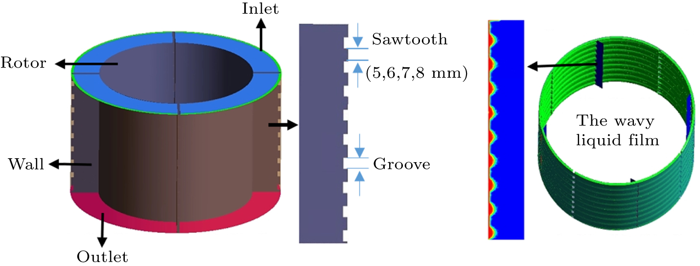
This research utilizes Fluent software for numerical simulations, ensuring that the primary model dimensions and associated process parameters align with those documented in the existing literature. This design has 100 mm in height, 120 mm in inner diameter, 164 mm in outer diameter, 2 mm in scraper width, and a 0.5-mm gap between the scraper and the evaporative wall. Owing to the model’s symmetrical nature, a quarter-periodic method is utilized, and tetrahedral elements[15] are used to create the finite element mesh in computational areas. The localized encryption is implemented on the wall and scraper front segments to record liquid film features.[16] Each wall is built under the no-slip boundary conditions.[17] After verification of grid independence, the minimum size is 0.4 mm and the total number of grids is 3.28 millions, the data remain relatively stable, the computational amount is reduced, and the errors are negligible. Five types of scraper structures are constructed, including straight type and sawtooth type. Within the sawtooth scraper, the groove sizes stay unchanged, maintaining a radial depth of 2 mm and an axial length of 5 mm. Changing the size of the sawteeth results in a unique liquid film shape. In the case of an in-line scraper, the liquid film remains flat along its axial segment. Figure 1 shows the ATFE comprehensive architecture and a diagrammatic illustration of the wavy liquid film formed by the sawtooth scraper.
The fluid under consideration is identified as an incompressible medium, with its evaporation predominantly controlled by variation in temperature. Considering the dual-phase gas and liquid movement in the ATFE, the simulations utilizes the volume of fluid (VOF) model[18]
For a two-phase flow, αl and αv represent the volume fraction of liquid and vapor in the VOF model. Then the density can be expressed as
where ρl and ρv represent the density of liquid states and the density of gas states, respectively.
Material flows into the inlet at a rate of 0.41 g/s. In contrast, the outlet uses the conditions of pressure boundary. The single motion reference frame model (SRF) is employed to achieve rotational movement, in which the fluid area spins at 120 r/min, the rotor speed relative to the fluid area remains steady at 0 r/min, and the outer wall’s absolute speed is maintained at 0 r/min. Given that the SRF determines the scraper’s rotation, it is essential to depict the governing equations (namely, continuity equation and momentum equation) within this system, with the equation for momentum conservation expressed as[19]
In this context, p represents static pressure, ρg and F denote the gravitational force and the external force, respectively,
where Ω × r represents the vector of angular velocity and r denotes the position vector within the rotating coordinate system. In the revolving reference framework, the equation for continuity is
It is crucial not to ignore the thermal transfer occurring in the ATFE. The formula for energy can be articulated as the variation in the system’s total energy per unit time, which is the sum of the net heat flow entering the system and the environmental work exerted on it and expressed as
where T represents the temperature, cpm denotes the specific heat capacity of wall material, ρm is its density and λm is the heat transfer coefficient. In this calculation, the wall material is selected as stainless steel.[20]
Considering the complicated shear current and rotational current in the ATFE, the k–ω SST (low Reynolds number turbulence model) yields more precise computational results than other models.[21] The model demonstrates proficiency in managing issues related to wall boundary layers, showing improved accuracy and algorithmic steadiness near the wall area. This model, extensively used in real-world engineering scenarios, has demonstrated its efficacy.[22]
-
The medium used for the simulation is the potato flour dispersion, known as a pseudo-plastic fluid.[15] The primary characteristic is the occurrence of shear thinning when exposed to shear force. In essence, the viscosity will swiftly decrease to an infinite shear level. Once the shear force vanishes, the viscosity will revert to zero shear, with rheological characteristics adhering to the power law model, as described in the equation
In this context, μ∞ represents the viscosity under infinite shear on a material; μ0 denotes the viscosity in the absence of shear; S (in unit s−1) indicates the rate of shear; k is the consistency coefficient; n is the non-Newtonian exponent, governing the non-Newtonian characteristic, n < 1 signifies the characteristic of shear thinning, and n > 1 denotes the characteristic of shear thickening,[15] as listed in Table 1 for the primary parameters of the simulated media.
Computation is streamlined by neglecting the influence of viscosity–temperature properties and material concentration (Conc.). The wall temperature is maintained at 110 °C, and the temperature at the inlet is 96 °C. The numerical analyses consider heat and mass transfer, with temperature variations primarily influencing evaporation. Consequently, we opted for the integrated approach of VOF and the Lee phase change model for the pertinent computations, with the detailed equations presented below:[23]
where Tsat is the saturation temperature, Tl is the liquid temperature, Tv is the vapor temperature, S symbolizes the mass transfer in evaporation or condensation. At the same time, t denotes the coefficient governing the intensity of evaporation process. Regarding boiling and condensation use in the real-world, the usual t span varies between 0.1 and 107. Yet, opting for a lower r-value is common when dealing with evaporative boiling scenarios.[24] Consequently, under these circumstances, a value of 0.1 is utilized, followed by the simulation of the evaporationonce the flow field reaches stability.
-
It is essential to confirm the dependability of the numerical model. This research utilizes the material outlined in Refs. [1,15] for the model validation. The specific attributes are shown in Table 2.
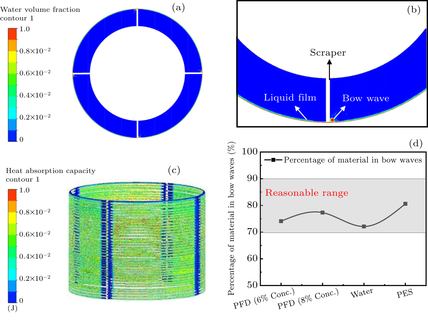
Figure 2(a) illustrates a cross-sectional view of the ATFE, with red signifying the liquid phase and blue indicating the gas phase. The bow wave is visible at the scraper’s front end in Fig. 2(b), a magnified view taken close to the scraper. The scraping motion of the scraper causes the material to disperse across the wall, forming a liquid film. Figure 2(c) describes the heat distribution during the evaporation of the material. Observations reveal that the bow wave absorbs only a slight amount of heat, suggesting that the liquid membrane primarily promotes evaporation in ATFE function. At the same time, the results in Fig. 2(d) show that the quantity of material in the bow wave accounts for 70%–90% of the total flow. These findings are consistent with Komori’s perspective.[25] The results mentioned above indicate that the computational outcomes in this study largely align with prior research’s theoretical findings, offering preliminary confirmation of the accuracy of the model presented in this paper.
2.1. Building of model
2.2. Simulation media and heat transfer modeling
2.3. Computational model alidation
-
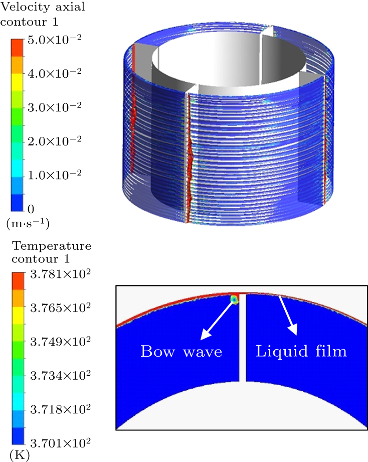
During the operation of the ATFE, at any location on the liquid film, there will be a periodic interchange of material with the bow wave caused by the action of the scraper’s scraping. Consequently, this finalizes the renewal process of liquid film, achieving effective evaporation. Figure 3(a) presents a diagrammatic representation of the material’s axial velocity distribution inside the evaporator. One can notice a significant disparity in the speed of the bow wave compared with that of the liquid film. The prolonged presence of the liquid film on the wall’s surface further suggests an extended period of heat exposure for the liquid film on the evaporative wall. In Fig. 3(b), the upward temperature distribution from the liquid film’s circumference is depicted near the in-line scraper. It is evident that during operation, the film’s temperature significantly exceeds that of the bow wave due to the liquid film’s extended heating duration on the evaporating wall. Echoing the pattern of heat absorption discussed earlier, this further indicates the significant involvement of the liquid film in the evaporation process.
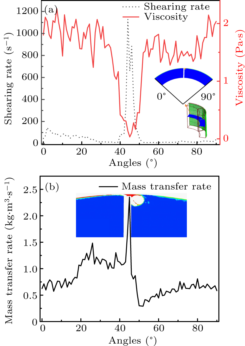
To better differentiate the liquid film’s evaporation capabilities at various locations, measurements of its viscosity and the mass transfer rate along the circumference are taken. Figure 4(a) clearly shows that during the operation of the evaporator, the scraper’s scraping action results in the highest shear rate and the lowest viscosity of the liquid film at the tip, which is attributed to the phenomenon of shear thinning. Additionally, the mass transfer rate refers to the evaporation rate at each point on the liquid film. It is used in this paper to measure the evaporation capacity at each point of the liquid film after shear thinning. Figure 4(b) shows the distribution of the liquid film’s mass transfer rate in the 90° area adjacent to the scraper in the cross-section, revealing that the liquid film’s mass transfer rate is higher in the area following the bow wave. The apex is attained close to the tip of the scraper, resulting in the liquid film being sheared at this point, thus reducing viscosity and facilitating evaporation. These findings demonstrate that the evaporation capabilities differ across different areas of the liquid film inside the evaporator, with the shear-thinning zone of the liquid film under non-Newtonian fluids outperforming other zones.
-
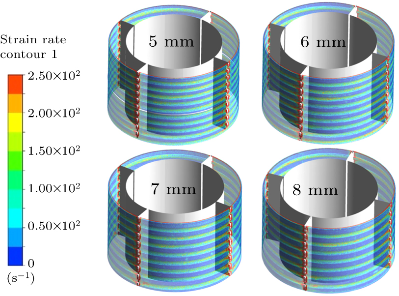
The shape of the liquid film in an agitated film evaporator dramatically influences its ability to evaporate. The material’s non-Newtonian nature results in the liquid film displaying rheological traits, with its ability to transfer heat differing across various sites. Consequently, traditional theories fall short of explaining how the thickness of liquid films affects heat transfer through evaporation. This research involves determining the liquid film’s shear rate by using Fluent’s post-processing software. The study above indicates that shear-thinning in the area created by the in-line scraper predominantly happens at the scraper tip, with a minor thinning zone where viscosity rapidly rebounds. The shear rates of the liquid film across various sawtooth lengths are depicted in Fig. 5. Studies indicate that the wavy liquid film formed by the sawtooth scraper experiences a significant shear in the groove zone, with negligible shears in other areas.
The phenomenon of shear-thinning is caused by the consistent arrangement of extensive polymer chains in the non-Newtonian fluid, which evolves from an initial entangled state to a structured formation along the direction of shear. The structured arrangement of polymer chains enhances the efficiency of heat transfer.
Within the realm of the research of surface scraping heat transfer, some researchers have conducted an in-depth analysis. They analyzed various models of heat transfer, and implemented adjustments, with more careful consideration of the scraping effect of the scraper and material properties and other factors. So in this study, the heat transfer model is utilized for assessing the liquid film’s heat transfer capability and the Nusselt number is expressed as[26]
In this context, Re is the Reynolds number, n denotes the scraper’s velocity in units of r/min, Ds represents the scraper’s diameter in units of m; Pr is the Prandtl number; cp refers to the specific heat capacity in units of J/(kg⋅K); λ means the material’s thermal conductivity in units of W⋅m−1⋅K−1.
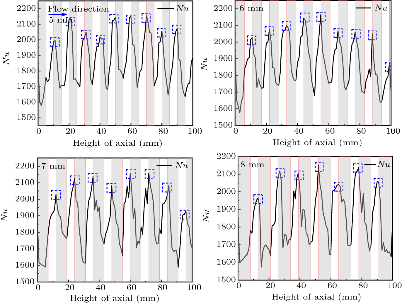
Figure 6 displays the axial spread of the Nusselt number in the wavy liquid film, derived from the analysis, with the shaded section representing to the sawtooth swept zone and the white section representing the grooved section. It is observed that the Nusselt number of the liquid film begins to decrease as the material moves through the area swept by the sawtooth. When the material exits from the sawtooth area and enters the groove area, the squeezing action of the sawtooth leads to a sudden change in the shear action. Especially at the crest of the liquid film, there is a rise in the Nusselt number, peaking precisely when it touches the subsequent sawtooth. The fluctuation in the shear rate at different points along the axial axis aligns with the changes in the Nusselt number.
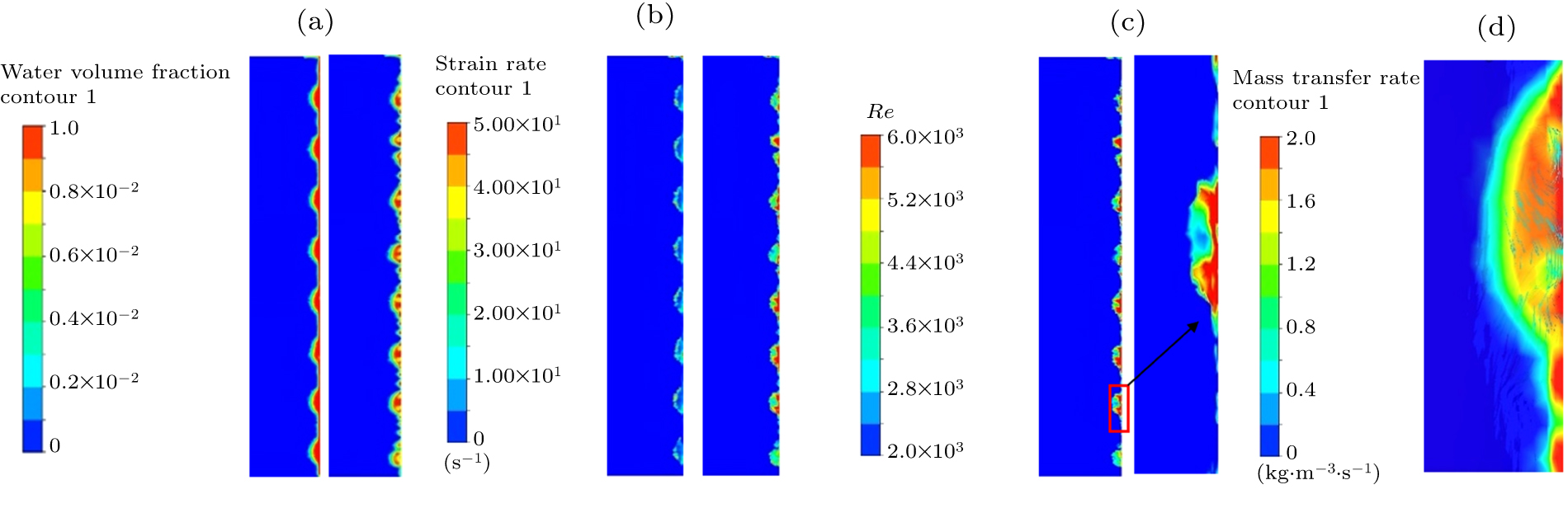
The findings mentioned above suggest that the ability of the liquid film to transfer heat through evaporation differs across its various areas. Figure 7 shows axial cross-sectional views of the wavy liquid film to demonstrate the variations in evaporation at different points. Figure 7(a) shows the comparison of condition between pre- and post-evaporation of the liquid film. We can notice the disruption of the liquid film at the scraper’s scraping site, leading to the formation of bubbles in the groove. Actions like the displacement and expansion of wall bubbles can diminish the ability of liquid film to transfer heat convectively. The change in the liquid film’s shear rate is depicted in Fig. 7(b). The shear force exerted on the liquid film is noticeable in the groove region, and this effect intensifies following evaporation, for which the reason is the reduction in the liquid film’s viscosity during the shear-thinning phase, which diminishes the intermolecular forces and amplifies the liquid film’s flow. In the case of non-Newtonian fluids, turbulence becomes evident once the stirring Reynolds number attains 300.[27] Additionally, figure 7(c) reveals that the liquid film in the groove experiences more significant agitation, and the thickening of this film at this point plays a role in the evaporation rate. As depicted in Fig. 7(d), the liquid film’s speed in the groove during evaporation appears chaotic, with its mass transfer rate in the groove marked by a high intensity near the wall and a moderate one at the edge. We can notice the presence of bubbles in the liquid film adjacent to the wall, accompanied by a weak effect of the mass transfer.
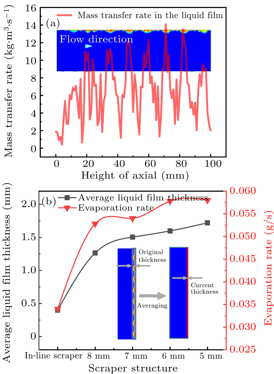
As evaporation occurs, the liquid film undergoes improved thermal transfer when subjected to shear forces due to decreased viscosity. Consequently, enlarging the area where shear thinning occurs can accelerate the evaporation speed of the liquid film. Figure 8(a) illustrates a statistical evaluation of the liquid film’s mass transfer rates at various elevations axially, using the wavy liquid film formed by the 7-mm sawtooth scraper as a case study. Observations indicate a heightened intensity of the mass transfer in the area where shear thinning occurs. Modifying the sawtooth’s configuration can enhance the liquid film’s shear-thinning area. Calculating the thickness of the wavy liquid film is challenging due to its wavy nature. Therefore, the aim is turned to determining the mean thickness, and the liquid film measurements shown in Fig. 8(b) represent the average thickness. Figure 8(b) shows the evaporation rate and the liquid film’s mean thickness in the ATFE under different scraper configurations. Observations show a relation between the variation in the liquid film’s average thickness and the evaporator’s evaporation speed. As the size of the sawtooth diminishes, the quantity of shear-thinning areas and the mean thickness of the liquid film are both increased, thereby enhancing the ability of evaporator to evaporate.
-
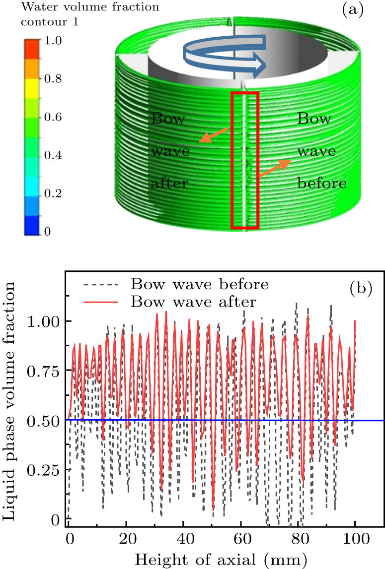
During the evaporation phase of the ATFE, the liquid film serves as the main area for heat transfer through evaporation, with its shape changing post-evaporation.[25] The findings above suggest that the liquid film ruptures the whole evaporation process. Variability in evaporation characteristics is observed in the liquid film surrounding the bow wave. Figure 9(a) depicts the spread of the flat liquid film across the wall during evaporation. Observations reveal that the liquid film demonstrates a contraction effect when this film is subjected to heat. Several drywall regions develop from top to down on the surface of the evaporating wall. In this context, ‘liquid film proportion on the wall’ is used to characterize the liquid film’s formation and denote the proportion of the wall’s liquid film area relative to the evaporated area. A threshold is established at a volume fraction of 0.5. When the liquid phase ratio exceeds 0.5, it is classified as a liquid film, facilitating the assessment of the liquid film’s percentage on the wall. A specific set of sample points is chosen axially to visualize the evaporation of liquid film before and after the bow wave. In the liquid film rupture analysis, a 0.5-volume fraction is used as the dividing line as depicted in Fig. 9(b). The investigations reveal a significantly greater number of points with a liquid phase volume fraction not exceeding 0.5 before the bow wave than that after. Notably, the liquid film preceding the bow wave exhibits a more pronounced breakage post-evaporation. The reason behind this occurrence is the non-renewal of the liquid film ahead of the bow wave over time, leading to an extended duration of exposure for the liquid film in this area. Conversely, the location of the liquid film situated behind the bow wave lies in the zone of renewal. The scraping action of the scraper causes the bow wave and the surrounding liquid film to blend and regenerate, making it challenging to break the liquid film in this region.
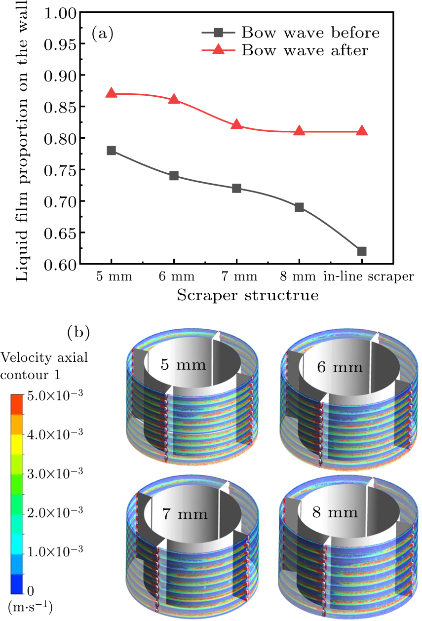
Changes in the shapes of liquid films significantly affect the ‘liquid film proportion on the wall.’ To explore how each liquid film evaporates, we analyze the percentage of the liquid film on the wall for each shape as depicted in Fig. 10(a). There is a regular occurrence of reduced occupancy in the liquid film preceding the bow wave. Before the bow wave, the ‘liquid film proportion on the wall’ in the flat liquid film is 62%. Yet, within the wavy liquid film generated by the 5-mm sawtooth scraper, the proportion increases to 78%, significantly exceeding that of the in-line scraper. Figure 10(b) illustrates the distribution of axial velocity for each wavy liquid film. The peaking liquid film in the groove exhibits a downward axial velocity. Due to its greater thickness, the liquid film in this region has a lower propensity to fracture during evaporation. It partially restores the underlying area, thereby enhancing the formation of the film on the wall.
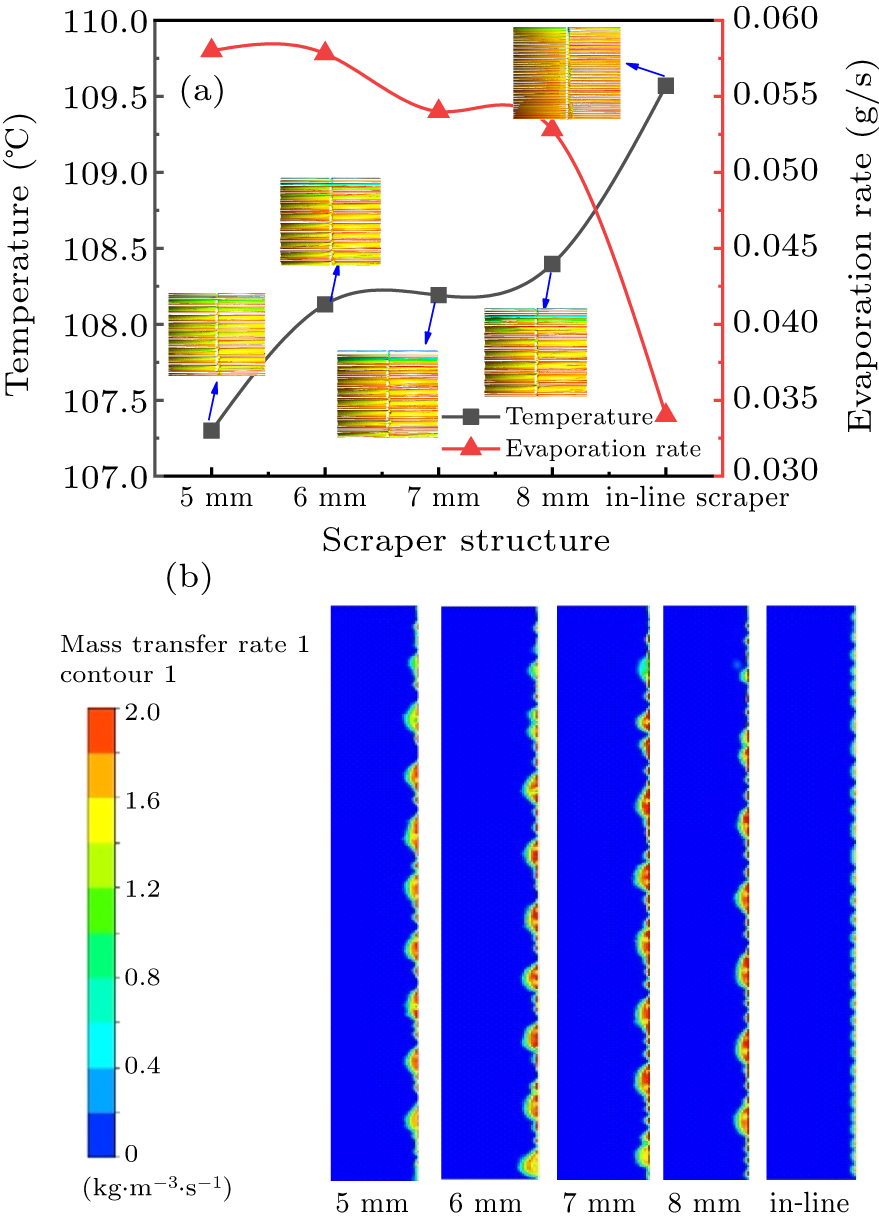
The influence of thermal conditions on the efficiency of evaporators throughout the evaporation process must not be overlooked. Figure 11(a) shows the contrast between temperature and evaporation of the liquid film, revealing an irregular temperature distribution on the film, where red indicates high temperature and green represents lower one. At the inlet, the liquid film’s temperature is reduced due to the ongoing influx of fresh material for its renewal. The flat liquid film’s final temperature surpasses other wavy films, attaining 109.5 °C. Formed by the 5-mm sawtooth scraper, the wavy film maintains a temperature of 107.2 °C, significantly influencing the evaporator’s production due to the temperature variance between the two films. When heated, the wave-resembling liquid film in the adjacent groove rejuvenates the sawtooth’s front liquid film. The motion of the liquid film leads the film’s total temperature post-renewal to decrease, subsequently influencing its formation. The mass transfer rates of various liquid films are depicted in Fig. 11(b), revealing that the wavy liquid film’s mass transfer rate markedly exceeds the flat liquid film’s, and the formation of the film on the evaporating surface is more thorough. As a result, the evaporator with the in-line scraper achieves the lowest evaporation rate of 0.034 g/s, unlike the 0.0528 g/s recorded with the 8-mm sawtooth scraper. The difference in evaporation rate demonstrates the ability of the wavy liquid film to evaporate efficiently in lower temperatures. Meanwhile, current studies indicate a logarithmic decrease in the time it takes for the liquid film to adhere to the wall as the temperature rises.[28] This phenomenon is manifested as a drywall effect in the ATFE, making the tube’s wall and the gas’s high temperature in direct contact with the tube’s wall prone to burning or deformation, thereby posing a risk to production.
3.1. Evaporation characteristics of flat liquid film
3.2. Evaporation characteristics of wavy liquid films
3.3. Formation of flat and wavy liquid films on wall
-
This work focuses on analyzing the shape of the liquid film. Our team conducted a comparison between a sawtooth-scraper and an inline-scraper agitated film evaporator and formulated the control equations. The shape of the liquid film and its evaporation process in multiple evaporator are examined, yielding some outcomes below.
(i) Evaporation primarily occurs in the liquid film, while the ability of the flat liquid film formed by the in-line scraper to evaporate differs at various locations. The liquid film in the scraper tip area experiences shear thinning, enhancing its evaporation efficiency compared with that in other areas.
(ii) Owing to the expanded area of shear thinning, the wavy liquid film exhibits remarkable evaporation capabilities, and augmenting the quantity of these areas can significantly enhance the evaporator’s evaporation capacity. Upon evaporation, the liquid film detaches from the sawtooth scrape. As the material transitions from the sawtooth to the subsequent groove zone, there is an abrupt shift in its shear rate, a change that becomes more pronounced during evaporation. Concurrently, with the turbulent movement of the liquid film, its ability to transfer heat is enhanced notably, leading the mass transfer rate to increase substantially.
(iii) The shapes of wavy liquid films in evaporation is more comprehensive than those of their flat counterparts. As evaporation occurs, the flat liquid film shows a more distinct break on the wall, and the appearance of drywall areas results in wall utilization reducing. Owing to the wavy liquid film formed by a sawtooth scraper, the overall shape becomes more complete, which is caused by the higher density of the peaking liquid film and its downward axial movement in its groove. The formation of the film is significantly improved, and its evaporation capability is enhanced.
 DownLoad: