
 首页
首页 登录
登录 注册
注册


HTML
-
Spinel lithium manganese oxide (LiMn2O4, LMO) has emerged as a promising cathode candidate for future large-scale stationary energy storage stations for lithium-ion batteries (LIBs), owing to its high operating voltage, inherent safety, moderate electrochemical performance, and most importantly, abundant resource availability that ensures excellent cost-effectiveness.[1–5] Significant attention has been dedicated to improving its performance ever since its potential application in LIBs was identified.[6–10] However, LMO faces the rapid degradation primarily driven by the Jahn–Teller effect, Mn dissolution, and related side reactions that degrade the electrolyte.[11] Doping and coating are commonly recommended strategies to stabilize the structure of the material and extend its cycle performance.[12–15] The leaching of Mn from Mn-based cathodes presents a significant challenge in improving performance, especially concerning LMO cathodes.[16–24] The consensus in the field acknowledges that Mn dissolution–migration–deposition (D-M-D) process in batteries has a detrimental effect on performance.[25] High-temperature (HT) environments can accelerate degradation processes. However, the mechanism remains unclear and is even contradictory across various studies.[26] Upon dissolution in the electrode, Mn will migrate towards the anode and subsequently undergo deposition. The presence of Mn in the electrolyte has the potential to destabilize the electrode. The deposition of Mn on or within the anode has the potential to catalyze the breakdown of the electrolyte, resulting in the formation of a thicker solid electrolyte interphase (SEI) layer. This phenomenon may impede the movement of lithium (Li+) ions within SEI through ion exchange, consequently leading to an increase in interface impedance.[24–26] A multitude of elements add to the complexity of understanding LMO battery degradation. Variability in the experimental setup, particularly in the type of batteries and the conditions under which they age, has been noted. Furthermore, there is a notable gap in research specifically focusing on commercial-level LMO batteries. This study aims to examine the capacity decay mechanism and the effect of Mn deposition on the anodes in commercial-level LMO batteries under various aging conditions.
-
Commercial-level LMO (BM2D, Boshi High-Tech, Anhui) and LiNi0.5Co0.2Mn0.3O2 (NCM, TLM550, Tianlilineng, Henan) were selected as the cathode materials, while graphite (QCG-X, Zichen, Jiangxi) was used as the anode.
-
LMO batteries were fabricated using a pilot production line and served as the focus of this study. LMO and NCM were combined in a weight ratio of 8:2 to serve as cathode active materials, as this configuration is frequently adopted in commercial-level LMO batteries. The cathode active materials underwent a drying process in a vacuum oven for 12 hours prior to utilization. To prepare the cathode electrode, the cathode active materials (LMO and NCM), super P (Timcal), CNT (LB100-50, Tiannai, Jiangsu), and polyvinylidene fluoride (PVDF, 5230, Sovlay) were initially dispersed in a weight ratio of 97.2:1.0:0.5:1.3 using N-methyl pyrrolidone (NMP, 99%, Aladdin) as the solvent. The solid content of the slurry was approximately 72%. The slurry was subsequently applied evenly to both sides of a 12 μm-thick aluminum foil to create the green cathode film. To prepare the anode electrode, the active material (graphite), super P (Timcal), carbon nanotube (CNT, LB100-50, Tiannai, Jiangsu), and a water-based binder (ADY-602, ADY, Ningbo, Zhejiang) were initially dispersed in a weight ratio of 94.7:0.5:4.8, utilizing deionized water (H2O) as the solvent. The solid content of the slurry was approximately 45%. The slurry was subsequently applied evenly to both sides of an 8 μm-thick copper foil to produce the green anode film. The cathode and anode electrodes were subsequently dried at 90 °C for 12 hours in a vacuum oven prior to cell assembly. Pouch cells were assembled in a low-humidity environment with a dew point below −40 °C, with electrolyte injection performed below −50 °C. The cell’s designed capacity was 14 Ah. Cell formation was conducted prior to the subsequent electrochemical evaluation. Typically, the cells underwent cycling at a 1 C rate at room temperature (RT) within the voltage range of 2.75–4.2 V. Subsequently, HT storage was conducted at 55 °C following a full charge to 100% state of charge (SOC). The study aims to investigate the effect of Mn deposition on the aging process of these cells. The cells that underwent formation, cycling, and HT storage were designated as fresh cells, RT cycle-aged cells, and HT storage cells, respectively. The aged cells were discharged to 0% SOC before being disassembled in an argon-filled glove box with H2 O < 0.1 ppm and O2 < 0.5 ppm. Subsequently, the electrodes were purified using dimethyl carbonate (DMC) and dried prior to additional characterization. To evaluate the reversible capacity or specific capacity of the cathode and aged cells, the cleaned electrodes were cut into 12 mm diameter discs for coin cell assembly. The CR2032 coin cells were fabricated within an argon-filled glove box at H2 O < 0.1 ppm and O2 < 0.5 ppm. The assembly included Li foil as the anode, the aged cathode/anode as the cathode electrode, and a polypropylene (PP) separator (25 μm). The electrolyte solution containing 1 M lithium hexafluorophosphate (LiPF6) in a mixture of ethylene carbonate/diethyl carbonate/methyl ethyl carbonate (EC/DEC/EMC, 1:1:1 by volume) was procured from Dongguan Shanshan. Subsequently, 70 μL of the electrolyte solution was dispensed into each coin cell. The cells were aged for 6 hours before testing to guarantee sufficient infiltration. To ensure the reliability of the coin cell data, three cells were assembled and measured. Small electrodes were cut from three different anode or cathode sheets, each derived from the disassembled full cell.
-
The galvanostatic charge/discharge cycling was conducted on a LAND BT2000 battery tester within the voltage range of 3.0–4.3 V. For the investigation of cycle and rate performance, the testing procedures for coin cells differed from the evaluation of fresh materials. Coin cells, assembled using disassembled anodes, were initially charged to 2 V versus Li. The resulting capacity obtained corresponded to the reversible Li inventory in the anode. Coin cells, assembled with cathodes, were initially discharged to 3 V versus Li. The resulting capacity obtained from this discharge corresponded to Li uptake of the cathode. Electrochemical impedance spectroscopy (EIS) measurements were performed using a Zahner Zennium Pro electrochemical workstation over a frequency range from 0.01–106 Hz, applying a 5 mV alternating current (AC) voltage perturbation. In order to facilitate the comparison of SEI impedance (RSEI) and charge transfer impedance (RCT), we set the ohmic impedance (ROhmic) to zero and transformed the EIS data into normalized impedance.
-
The cathode and anode were analyzed using powder x-ray diffraction (XRD, Bruker D8 Advanced) to determine their phases and examine the evolution of their crystal structures. The morphology and microstructure were examined using scanning electron microscopy (SEM, Hitachi Regulus 8100). Energy dispersive spectroscopy (EDS) was utilized in SEM to investigate the elemental distribution across the cathode samples. X-ray photoelectron spectroscopy (XPS, PHI 5000 Versaprobe III) was employed to analyze the composition and valence states of the cathode surface. Raman spectra were analyzed using a Renishaw inVia reflex Raman microscope. Transmission electron microscopy (TEM) images were collected on a field emission TEM (FEI Tecnai F20).
2.1. Materials
2.2. Cell fabrication
2.3. Electrochemical test
2.4. Material characterization
-
The electrochemical performance of the cells was evaluated through constant current charge/discharge cycles and dQ/dV analysis. Figure 1 illustrates the typical profiles obtained from these measurements. As shown in Fig. 1(a), the pristine cells exhibited typical charge–discharge behaviors of LMO cathode-based batteries, featuring two discharge plateaus at 4.06 V and 3.89 V, with two charge plateaus around 3.91 V and 4.06 V. The reversible discharge capacities were measured at 13.16 Ah and 12.49 Ah at rates of 0.05 C and 1 C, respectively, meeting the specified design requirements (
Table S1 ). The pouch cell demonstrated a cycle life of approximately 1000 cycles while retaining 80% of its capacity at the end of its lifespan. This represents the typical commercial level for LMO LIBs, where the active cathode materials commonly consist of a blend of LMO and NCM (Fig. 1(b)). Capacity degradation can stem from various factors, such as the loss of active materials, phase transitions of active materials, damage to the microstructure of electrodes, electrolyte depletion, Li inventory reduction, and increased impedance. Further investigations were conducted to demonstrate the effect of these factors. The charge–discharge profiles of RT cycle-aged cell (1 C rate cycle at RT) are contrasted with those of the fresh cell at 0.05 C and 1 C rates (Figs. 1(c) and 1(d)). The aged cell in the cycle provides 11.19 Ah at 1 C rate and 11.51 Ah at 0.05 C rate (Table S1 ), resulting in a 12.54% reduction in capacity. The results indicate the existence of polarization that impedes the migration of Li ions during the charge–discharge process, leading to a decrease in capacity. Cells incubated at 55 °C for 7 days were selected for examination. Figure 1(e) depicts the charge–discharge profiles of freshly manufactured batteries and batteries subjected to HT aging, both evaluated at 0.05 C rate. Exposure to high temperatures caused a 6.99% capacity loss, resulting in 12.24 Ah instead of the expected 13.16 Ah for newly manufactured batteries. As demonstrated in Fig. 1(f), a comparison of battery capacities under various conditions reveals that fresh batteries exhibit a higher capacity. The dQ/dV analysis is obtained from the charge–discharge profiles of fresh and RT cycle-aged cells at 0.05 C rate. Figures 1(g)–1(i) show two additional oxidation peaks at 3.75 V and 4.02 V. Furthermore, the existing oxidation peaks show a slight shift towards higher potentials, measuring 3.92 V and 4.08 V, in contrast to 3.91 V and 4.06 V for the new cell. The intensity of oxidation is significantly diminished. The test results indicate that part of the active materials might have peeled off from the electrode or undergone a phase change during the cycle test. The storage of LMO cathode-based batteries at high temperatures presents a significant challenge. Two novel oxidation peaks appear at 3.75 V and 4.03 V, whereas the pre-existing oxidation peaks have shifted marginally towards higher potentials at 3.92 V and 4.07 V in contrast to 3.91 V and 4.06 V for the pristine cell. The oxidation intensity has decreased significantly. The data indicates that the active ingredients underwent a phase transition during a 7-day storage period. The shift in the oxidation/reduction peaks may be attributed to increased polarization.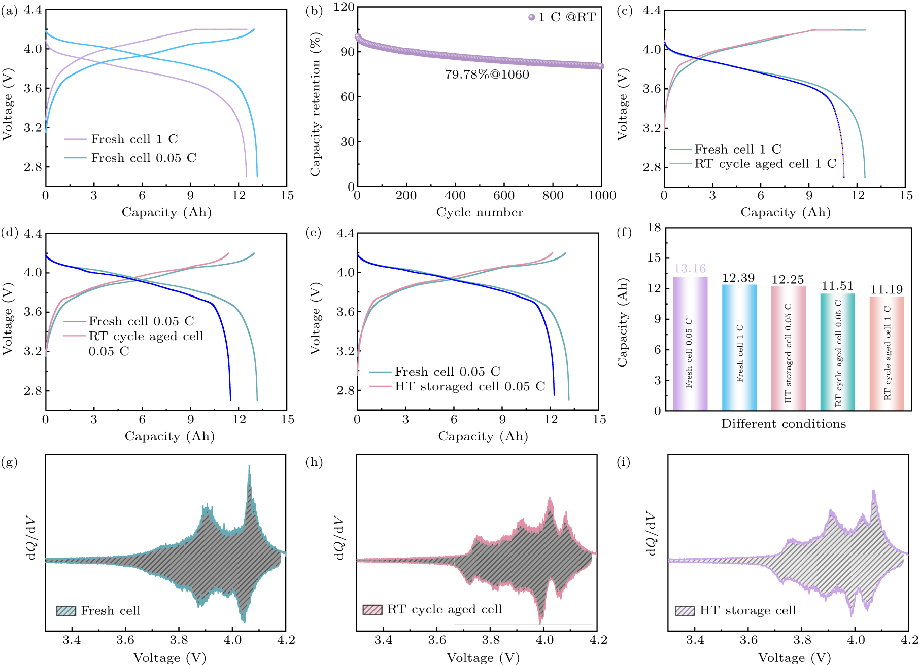
To elucidate the evolution of both anode and cathode materials, XRD data were collected and compared for the three cell samples. As illustrated in Fig. 2(a), XRD patterns exhibit no discernible variance; LMO maintains its spinel phase and NCM its layered phase in both RT cycle-aged and HT storage cells, although the dQ/dV curves suggest potential phase transitions in the active material. Upon closer examination of the zoomed-in XRD patterns (
Fig. S1 ), the only significant deviations are a peak shift at approximately 2θ of 18.54° (associated with (003) peak for NCM) to lower 18.42°, and the (111) peak for LMO diffraction peak shifts from 18.70° to 18.72° for the RT cycle-aged cell. These shifts are likely attributed to Li deficiency resulting from both reversible and irreversible Li retention tracked in the anode. For the cathode from HT stored cell, the (003) diffraction peak position for NCM remains nearly unchanged, while the (111) diffraction peak position shifts from 18.70° to even higher 18.78°, meaning much more Li deficiency for LMO. The results suggest these changes primarily originate from surface reactions. Furthermore, Tang et al.[22] documented that the spinel LMO surfaces underwent phase transformations to Mn3O4, where Mn2+ exacerbated side reactions, ultimately resulting in capacity loss. However, as discussed in the next section, the capacity loss resulting from phase changes in the cathode is not the primary factor contributing to cell capacity degradation. XRD patterns obtained for the three anodes show no discernible bulk phase alterations (Figs. 2(b) andS2b ). As shown in Fig. 2(c), Raman spectra were also obtained for the three anodes. The peak at 1346 cm−1 is the D peak and the peak at 1581 cm−1 is the G peak. The ID/IG is obtained by normalizing to the G peak intensity, as shown in Fig. 2(d). The higher ID/IG indicates decreased graphitization degree, while a lower value corresponds to higher graphitization. In Fig. 2(d) andTable S2 , the ID/IG are 0.52 and 0.42 for anodes from RT cycle-aged and HT storage cells, which are much larger than 0.37 for the anode from the fresh cell. Similarly, the D′ peak at about 1620 cm−1 is also an indicator of increased graphite disorder. The relative intensity of the D′ peak also increases in both RT cycle-aged and HT storage cells (Fig. 2(c)).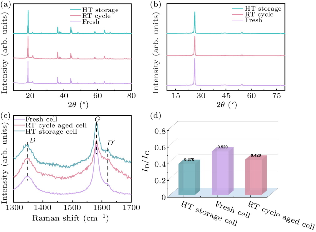
These results indicate that the degree of disorder increased in the graphite, at least at the surface of the graphite anode. This may be related to the structural destruction of graphite due to continuous lithium intercalation and de-intercalation, co-intercalation of solvent molecules, and the formation of SEI on the graphite surface. The higher ID/IG for the anode from RT cycle-aged and HT storage cells also confirm this trend, as shown in Fig. 2(d).
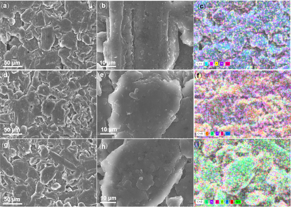
The microstructures of the cathodes (Fig. 3) and anodes (Fig. 4) were examined using SEM. Figure 3 shows that, apart from certain cracks in the cathode composite of RT cycle-aged cell, no significant changes were observed. These cracks are considered one of the typical degradation mechanisms for cathodes. However, the anodes from RT cycle-aged and HT storage cells, as depicted in Figs. 4(b)–4(h), exhibit a substantial SEI layer, as corroborated by the results of EDS mapping. The sum concentrations of fluorine (F) and oxygen (O), which are the representative elements of SEI, in the aged cell cycle are approximately double those found in the fresh cell. The levels in HT storage cell fall between the values of fresh and aged cells. These observations are recognized as common features of SEI formation (
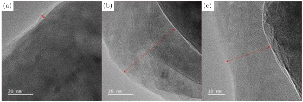
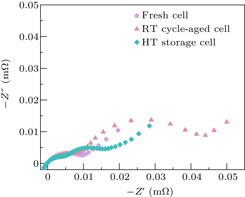
Table S3 ). The presence of a thick SEI suggests the occurrence of significant side reactions at the interface between the electrode and the anode during cycling and HT storage. TEM analysis of the anodes is shown in Fig. 5. We can see from Figs. 5(a) andS2 , the thickness of SEI is about 2–6 nm, 45–55 nm, and 25–35 nm for the fresh cell, RT cycle-aged cell, and HT storage cell, respectively. The thick SEI indicates that severe side reactions occurred at the electrode-anode interface during cycling and HT storage. The EIS analysis results are consistent with the TEM observation (Figs. 6 andS3 and Table S4 ). We can see that the SEI resistant (RSEI) of RT cycle-aged cell is 4 times larger than that of the fresh cell, while RSEI of HT storage cell is over 2 times larger than that of the fresh cell. According to previous reports, transition metal ions such as Ni, Fe, Co, and Mn dissolving from the cathode and depositing on the anode can induce significant side reactions in LIBs.[10] The dissolution of Mn from Mn-based cathodes poses a significant challenge to enhancing performance, particularly in the case of LMO cathodes. The consensus in the field acknowledges that the Mn D-M-D process in batteries has a detrimental effect on performance.[28] However, the mechanism remains unclear and even contradictory across various researches. Upon dissolution in the electrode, Mn2+ ions will migrate towards the anode, where they will be subsequently deposited. The presence of Mn in the electrolyte has been documented to induce instability in the electrode. Mn deposited on or within the anode serves as a catalyst for electrolyte decomposition, leading to the formation of a thick SEI layer. Additionally, it hinders the transport of Li+ ions within SEI through ion exchange processes, consequently elevating the interfacial impedance. Multiple factors contribute to the state of chaos. Existing studies vary significantly in battery samples and aging conditions. To our knowledge, no systematic study has addressed commercial-level LMO batteries. Therefore, this study examines the effect of Mn deposition on the anodes of commercially available LMO batteries at a practical level.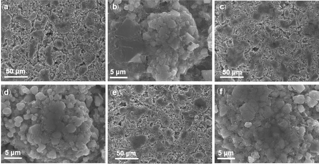
The powders obtained from the three anodes post-cleaning and drying were analyzed using inductively coupled plasma (ICP). The results are presented in Table 1. Mn content in the anode of RT cycle-aged cell can reach up to 1922 ppm, while the fresh cell (after formation) shows 140 ppm. Notably, Mn was also identified in the anode of HT storage cell, a presence not observed in the fresh cell according to EDS analysis. The results obtained from ICP are consistent with expectations, given that aging, cycling, or HT storage are known to accelerate the D-M-D process. In contrast, SEM/EDS analysis detected no Co or Ni. Their deposition levels are two orders of magnitude lower than that of Mn (Table 1), presenting ICP analysis results. Furthermore, the deposition of Ni and Co on the anode shows minimal increase in HT storage cell compared to that of the fresh cell. Therefore, it is logical to infer that the dissolution and deposition of Ni and Co do not primarily contribute to the side reactions causing capacity degradation.
Due to the inability to perform quantitative analysis of the phase identified in this complex system, lithium half-cell testing was conducted to evaluate reversible/specific capacities of anodes and cathodes for identifying capacity degradation sources. Coin cells were assembled using electrodes disassembled from three cells. For cathodes, specific capacity was measured, while anode capacity was assessed based on electrode area due to the impracticality of weighing active materials. To prevent cross-contamination, one side of the double-sided anode was covered with conformal Cu tape.[27–29] The testing procedures differed from the assessment of newly acquired materials. Coin cells, assembled using disassembled anodes, underwent an initial charging process. The resulting capacity reflects the reversible Li content within the anode. Coin cells assembled with cathodes underwent an initial discharge process to determine the capacity associated with Li absorption by the cathode. To enhance credibility, three coin cells were manufactured for each anode and cathode from the three cells. As shown in Fig. 7 and
Table S5 , the level of data consistency is sufficient to validate the reliability of this method. Cathodes serve as the exclusive source of reversible Li inventory in LIBs.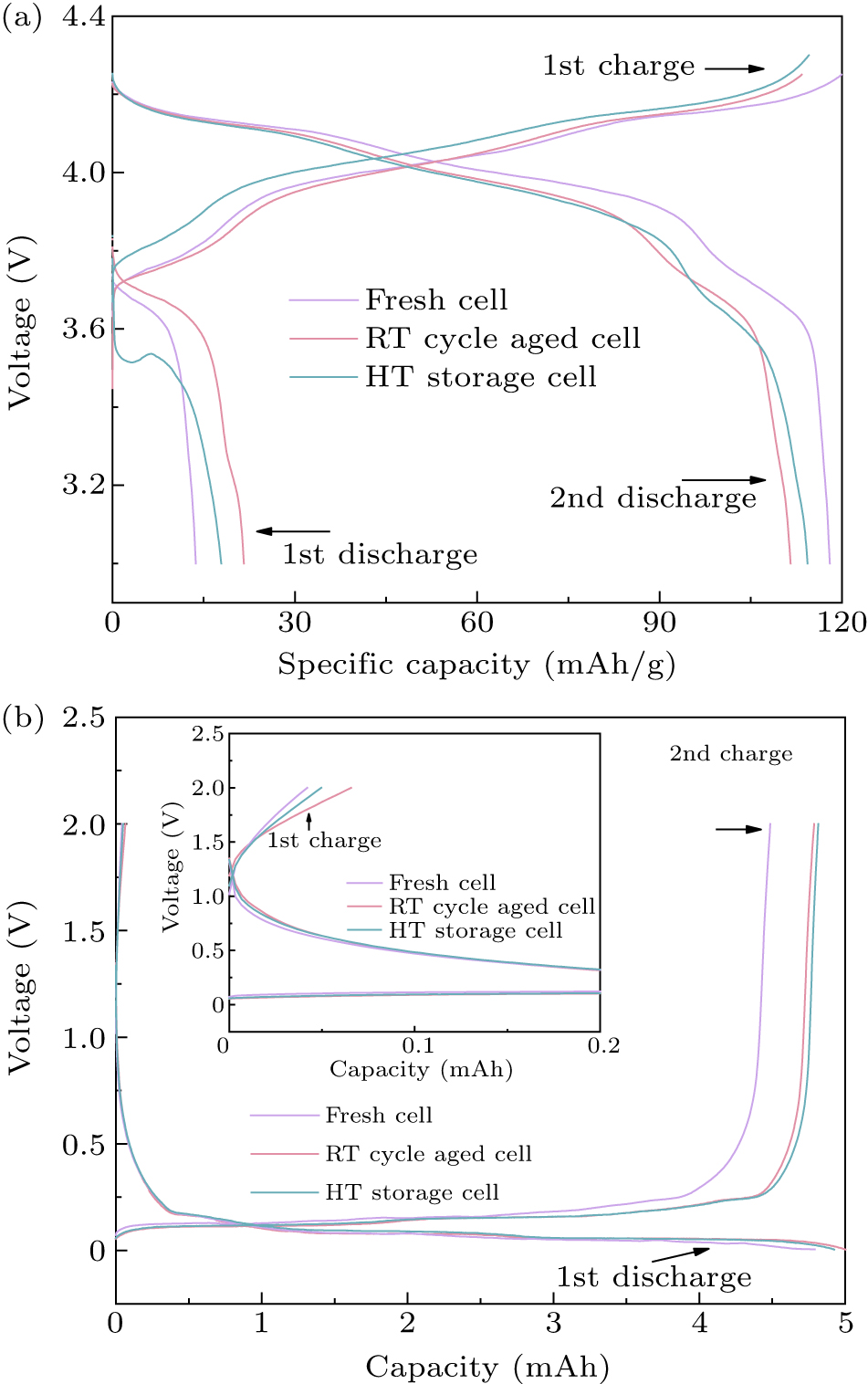
The formation and subsequent aging processes lead to continuous Li inventory consumption, ultimately causing a reduction in capacity. The test results presented in Fig. 7(a) and
Table S5 demonstrate increasing Li deficiency with the batteries aging, consistent with the XRD results from the aged cathodes. Side reactions, such as the formation of SEI, dendrites, and significant polarization, can exacerbate the situation. On one hand, the cathodes from RT cycle-aged and HT storage cells exhibit approximately 6.26% and 2.55% specific capacity loss in comparison to fresh cell, respectively. These values are lower than the capacity loss observed in RT cycle-aged (12.54%) and HT storage cells (6.99%). Conversely, the reversible capacities of the three anodes measured closely resemble that of the fresh cell (Fig. 7(b)). This demonstrates a specific quantity of reversible Li inventory within the anode, and indicates that the aging process of the cycle and the storage of HT do not lead to permanent capacity reduction on the anode side. The results from the coin cell experiments suggest that the primary causes of irreversible capacity degradation are not attributed to the cathode and anode. The deposition of Mn on the anode, along with associated side reactions that deplete the electrolyte and form a thick SEI, contributes to the loss of Li inventory in LMO batteries. This includes reversible Li that becomes trapped in the anode, ultimately resulting in a decrease in capacity.To ensure credibility, three different coin cells were fabricated for each anode/cathode taken from the three cells. As shown in
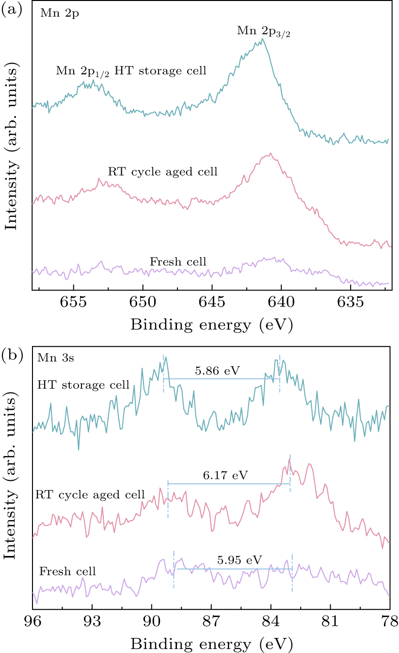
Table S5 , we can find that three data sets have excellent battery performance. This is enough to prove the possibility of making batteries from anode material. Similarly, the cathode material used in this method also has good electrochemical performance (Table S5 ). As cathodes are the only source of reversible Li inventory in LIBs, continuous Li consumption during formation and aging progressively reduces capacity. According to the test result in Figs. 6(a)–6(c), the Li deficiency increases as batteries age.XPS was employed to examine the composition and valence state of the anode surface. Anode samples were transferred to XPS after being subjected to an inert protection environment prior to spectrum collection. Mn 2p spectrum exhibits complexity attributed to overlapping binding energies, multiplet splitting, and asymmetry in the spectrum. Obtaining the valence information of Mn solely from the Mn 2p spectra poses a challenge. Mn 3s spectrum is frequently examined due to its higher sensitivity to the oxidation state of Mn compared to Mn 2p. Mn 2p and Mn 3s spectra were obtained for anodes sourced from fresh, RT cycle-aged, and HT storage cells as shown in Fig. 8. The intensity of the Mn 2p3/2 peak is low, while the Mn 2p1/2 peak is barely detectable. This observation may be attributed to the low Mn deposition content in the fresh cell. The Mn 2p3/2 peaks of the three anodes appear at approximately 640.7 eV, 640.9 eV, and 641.4 eV (Fig. 8(a)). The differences in binding energy values (ΔE3s) between two Mn 3s peaks are 5.95 eV, 6.17 eV, and 5.86 eV for deposited Mn on anodes from the fresh, RT cycle-aged, and HT storage cells (Fig. 8(b)). Elke et al.[30] introduced a method to calculate the average oxidation state of Mn (VMn) through the equation (VMn = 9.67–1.27ΔE3s). Then the average oxidation states are 2.22, 1.83, and 2.11, respectively. These values suggest that Mn deposition in this case is divalent, rather than metallic.[31] To extend the lifespan of LMO cathode-based LIBs, additional research endeavors should be directed towards mitigating the Mn D-M-D process.
-
In this research, commercial-level LMO batteries were developed with an evaluation of their electrochemical performance. This study focuses on unraveling the mechanisms behind capacity reduction in cells subjected to both RT cycle aging and HT storage. The results demonstrated that alterations in the crystal structures and phase transitions in the cathode and anode materials contribute to the overall capacity degradation. Notably, the study identified that significant polarization, primarily resulting from the continuous growth of the SEI layer, plays a more crucial role in reducing battery efficiency. This SEI growth, alongside the accompanying depletion of Li inventory and increased electrolyte consumption, appears to be exacerbated by the deposition of divalent Mn on the anode surface. The results indicate that this Mn deposition, present in both RT cycle-aged and HT storage cells, is likely a key catalyst in the SEI formation process. In the future, the focus will be on inhibiting manganese from dissolving from the positive electrode and entering the electrolyte, and doping and coating are two good improvement directions.[32]
 DownLoad: