
 首页
首页 登录
登录 注册
注册


-
核能因其具有清洁高效的特点而被认为是现代社会最有前途的能源之一[1]。在探讨下一代核反应堆燃料时,氮化铀(UN)由于其具有低热膨胀[2]、高裂变密度[3]、良好的热导率[4]、高熔点[5]以及与大多数潜在包层和冷却剂材料的兼容性等特性,而作为事故容错燃料备受关注[6-7]。然而,尽管UN在许多方面具有潜力,但由于其具有一定的化学毒性和放射性[8-9],在实验室直接进行UN实验存在一定的安全风险,并且成本较高。为了降低研发成本并减少对研究人员和环境的潜在伤害。通常可以考虑寻找一些理化性质与UN相近的替代材料进行探索,以降低成本、提高安全性,这将可能为核能技术的可持续发展铺平道路[10-11]。
由于稀土元素铈(Ce)的价电子层结构与铀(U)相似,Ce被认为是模拟U的较为理想的材料之一[12-15]。迄今为止,国内外已展开了大量利用Ce模拟U的相关研究。Stennett[16]利用CeO2代替二氧化铀(UO2),进行UO2粉体的致密化行为研究;罗丽珠等[17]研究探讨了利用金属Ce模拟替代锕系元素U的可行性,分析认为金属Ce与U的氧化过程相似,即金属Ce与U的氧扩散方式相同,且二者有基本相同的表面氧化层结构;Logan Joyce等[18]利用CeN模拟了UN的烧结,利用一种快速加热系统极大程度的减少了CeN烧结过程中的氧化,制备的CeN球团致密度高且结构均匀。综上所述,已有大量研究证明Ce可以有效的替代U进行模拟研究。与此同时,CeN的理化性质在多个方面都与UN表现出良好的相似性。这些相似性包括熔点(UN为2757℃,CeN为2480℃[19])、热膨胀系数(UN为7.481×10⁻⁶ K−1,CeN为30×10−6 K−1[20])、表面氧化过程以及氧化层结构[18]等,CeN也是用于模拟UN的良好候选材料[21]。但是,由于CeN的化学性质非常活泼,这对CeN的研究和使用都造成了极大的困难。宛悦等[22]研究了在CeN在大气环境下的氧化行为,发现CeN薄膜与氧气接触后短时间内便会粉化脱落。梁威等[23]对Ce基片表面进行了氮化改性以希望提高Ce的抗腐蚀性能,但发现CeN本身便极易氧化,故在氮化处理后的样品表面进一步沉积陶瓷抗氧化层氮化钛(TiN),得到的复合薄膜有着良好的抗氧化性能。为了促进CeN模拟UN的研究,利用制备抗氧化膜层的方法来改善CeN薄膜的氧化腐蚀问题,以增强其在环境中的稳定性。
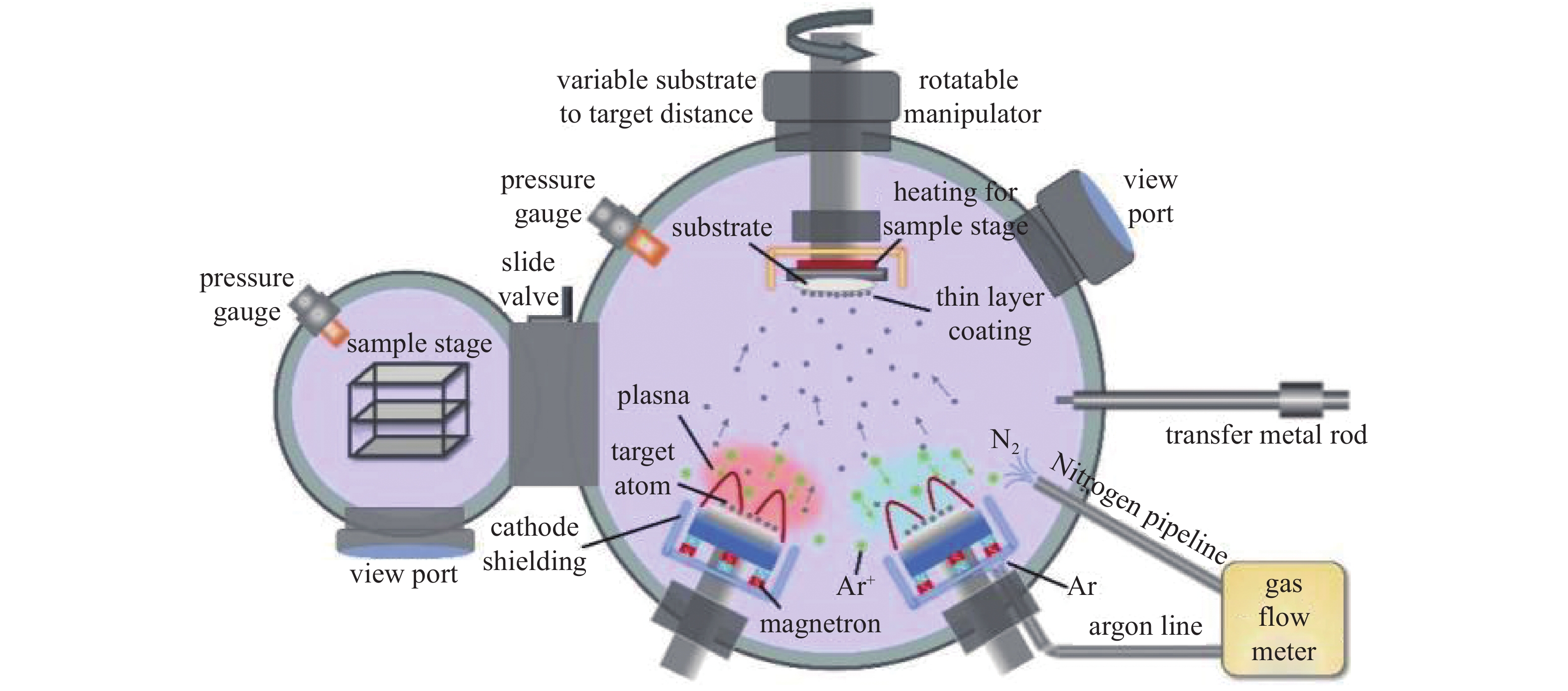
钛(Ti)和铬(Cr)由于其优异的性质,例如高机械强度[24]、出色的热稳定性[25]、在极端条件下良好的耐腐蚀性[26]和内在的生物相容性,是生物医学、航空航天和许多工业应用中用作散装或涂层的重要候选材料[27-28]。本文的研究将采用磁控溅射技术制备CeN薄膜,并利用磁控溅射在其表面制备Cr和Ti金属抗氧化膜层,研究这些膜层对CeN薄膜抗氧化性质的影响。探讨抗氧化膜层对CeN薄膜氧化行为的影响规律和机制。通过这项工作,希望为CeN模拟UN的研究以及相关应用提供有价值的参考。
-
在不同溅射功率条件下制备的CeN薄膜XRD谱图如图2所示,所有样品均在暴露大气10 min内完成测试。将XRD图谱与CeN的标准PDF卡片(PDF#89-5220)和CeO2标准PDF卡片(PDF#43-1002)进行比较发现溅射功率从50 W到200 W,XRD图谱都仅存在28.5°一个峰,28.5°处的峰对应于CeO2的(111)面,但随着功率升高到250 W,特征峰明显右移至29.1°,这个峰对应于CeN的(111)面。
将CeN薄膜从真空室取出后,迅速放置在光学显微镜下观察。观察结果如图2插图所示,仅仅过去5 min,薄膜便已完全氧化损坏。
-
在单晶Si基底上研究了Ti单层薄膜的沉积工艺。为了模拟真实U部件表面实际沉积温度要求,作者在常温下制备了Ti膜,并选取50 W、150 W和250 W的溅射功率分别溅射1 h制备了Ti薄膜。其XRD图谱如图3(a)所示,当溅射功率为50 W时,由于功率太低薄膜呈无定形态,XRD图像中没有属于薄膜的衍射峰;而在150 W和250 W时,除38.4°的Ti (002)衍射峰外,未出现其他峰,表明此时薄膜沿(002)择优取向生长。
随着沉积功率的改变,薄膜的表面形貌和粗糙度同样发生了非常明显的变化。样品在不同沉积功率下的表面形貌如图3(c)、(e)和(g)所示。当沉积功率为50 W时,样品表面均匀分布有小坑,但小坑深度较浅,薄膜整体较为均匀;当功率增加到150 W时,薄膜表面少量晶粒异常长大,导致粗糙度明显增加;当沉积功率继续增大到250 W,样品较平整,无明显缺陷或大晶粒,但表面逐渐呈砂砾状,粗糙度增大,可能的原因是较大的功率导致薄膜的生长速率较快,从而导致其粗糙度增加。当沉积功率从50 W升高到250 W的过程中,表面粗糙度变化分别为3.672 nm、13.82 nm和16.8 nm,如图3(b)所示。由于Ti薄膜的溅射速率与薄膜粗糙度几乎呈正相关,考虑到最终需要微米级抗氧化层和尽可能低的粗糙度,最终选取150 W的功率制备CeN的抗氧化涂层。
采用150 W功率在CeN表面原位制备了不同厚度的Ti膜,在光学显微镜下观察其氧化过程,如图4所示。观察发现,所有样品在暴露大气后均出现了破损。如图4(a)(b),20 nm Ti/2 μm CeN复合薄膜在接触空气后迅速粉化,其氧化速度甚至远快于单层的CeN薄膜。这可能是由于溅射的Ti抗氧化层在较薄时薄膜中存在少量的针孔,从而容易吸附空气中的氧气,对CeN的氧化起到一定的促进作用[29-30]。如图4(c)-(f)所示,200 nm Ti/2 μm CeN和600 nm Ti/2 μm CeN复合薄膜,薄膜表面尚未出现明显氧化现象时,薄膜界面处开始碎裂分解,并迅速扩散至整个薄膜。可能是当薄膜整体较为完好时,薄膜还有着较高的硬度,此时薄膜界面处的氧化导致结构被破坏,最后导致大面积碎裂。1.2 μm Ti/2 μm CeN复合薄膜在接触空气后表面出现大量细密的小孔,且在30 min后薄膜表面出现大量隆起,且峰顶处有孔洞形成。由于Ti薄膜的表面存在空隙,这将利于氧气的进入从而导致CeN被氧化。而氧化过程中释放的氮原子又因为Ti薄膜表面氧化形成了致密的TiO2被困在氧化层内或界面处,从而产生气孔或分层,导致薄膜表面形成大量隆起[31]。而2.4 μm Ti/2 μm CeN复合薄膜随着在空气中暴露时间的增加,表面从光滑平整逐渐变得粗糙,并生成少量孔洞,且薄膜也出现了轻微起伏。室温下制备的金属Ti薄膜无法对CeN薄膜起到有效的保护,可能主要是由于制备温度较低,薄膜的整体致密度较差,且Ti本身容易吸附空气中的氧气,从而导致了底层CeN的氧化。
-
同样的,首先在Si基底上制备了Cr单层薄膜,分别选用了50 W、150 W和250 W这三种溅射功率分别溅射1 h,Cr的X射线衍射图谱如图5(a)所示。可以看到,三种功率下的Cr薄膜都只有44.39°一个特征峰,与Cr的PDF# 06-0694比对一致。提高沉积功率后,Cr的沉积速度提高,导致Cr厚度明显增加,所以在增加溅射功率后,Cr的衍射峰显著增强。
为了更好的研究Ti和Cr作为CeN抗氧化层的区别,同样使用了原子力显微镜对Cr薄膜进行了表征,如图5(c)−5(h)所示。相较于Ti薄膜,Cr薄膜表面要更为平整致密,且在增加功率之后,粗糙度也只是略有增加。可能是因为Cr的溅射速率约3倍于Ti的溅射速率,较快的溅射速率可以在同样的时间内获得更厚的抗氧化层,如图5(b)所示,这也使得Cr在工业上有更广阔的运用。考虑到最终需要较厚的抗氧化层,同时也需要抗氧化层有比较低的粗糙度,所以本文后续Cr薄膜沉积过程均采用溅射功率150 W条件制备。
利用磁控溅射在CeN上制备了不同厚度的Cr抗氧化层,在保持CeN厚度不变的情况下,分别制备了5种厚度的Cr抗氧化层,即20 nm Cr/2 μm CeN、200 nm Cr/2 μm CeN、600 nm Cr/2 μm CeN、1.2 μm Cr/2 μm CeN和2.4 μm Cr/2 μm CeN,分析比较5种样品的抗氧化性能,希望获得对CeN保护效果最优的薄膜体系。
图6给出了磁控溅射溅射沉积制备的不同厚度的Cr/CeN双层复合薄膜的X射线衍射图谱,所有样品均在接触空气后10 min内测试。可以看到随着溅射时间的增加,Cr的(110)衍射峰有着明显的增强,由于变量仅仅是溅射时间,推测衍射峰增强的主要贡献是来源于厚度的增加。图6(b)是5组Cr/CeN复合样品的20° ~ 35°的X射线衍射图谱的局部放大图,从20 nm到1.2 μm的Cr/CeN复合薄膜可以看出,样品的衍射峰从一开始的CeO2 (111)面逐渐向CeN的(111)面移动,而2.4 μm的Cr/CeN抗氧化层在25°到30°未出现任何峰,可能是由于此时Cr膜太厚,削弱了CeN的衍射信号。
图7为在CeN上沉积不同厚度的Cr薄膜表面的光学显微镜图片和实物照片。从图7(a)中可以看出,20 nm的Cr/2 μm CeN复合薄膜在30 min时,表面就已出现大量细密的凸点。且薄膜表面已开始大面积起皮脱落,基片表面仅残余少量薄膜。而200 nm Cr/2 μm CeN、600 nm Cr/2 μm CeN、1.2 μm Cr/2 μm CeN复合薄膜在30min后,薄膜表面都出现了大量细密的气孔,从宏观图片也可以看到,薄膜此时已发生不同程度脱落。2.4 μm Cr/2 μm CeN复合薄膜可以在大气环境中存放12 h而不发生明显变化,如图7(e)所示。
为进一步探究2.4 μm Cr/2 μm CeN复合薄膜的氧化行为,对Cr/CeN复合膜的截面和表面进行了SEM测试,如图8所示。与单独溅射Cr相比,Cr/CeN复合薄膜中Cr的表面形貌要稍显稀疏,从截面看复合薄膜有着清晰的界面,且CeN形貌成无定形状态,Cr有着明显的柱状生长形貌,这样氧分子可能从这些空隙中进入薄膜内部,从而导致CeN的失效。基于以上分析,提出了一种CeN复合薄膜一种可能的氧化机制,如图9所示,由于复合薄膜中Cr不够致密的表面形貌使其无法形成致密的保护层以阻止氧气进入,而氧气从薄膜的间隙中进入后首先与CeN薄膜表面发生物理吸附,随之CeN薄膜与氧反应生成Ce氧化物,O原子取代了N原子后,形成的氧化物(CeO2)与CeN,使薄膜内部出现大量的晶格畸变,体系混乱度增加,稳定性降低。同时被氧取代的过量的氮原子可以积累沿晶界迁移,结合形成氮气,最后导致表面气孔的形成。
-
本文通过磁控溅射在CeN表面沉积Ti或Cr薄膜,研究其对CeN薄膜氧化的防护作用。在CeN上沉积Ti抗氧化层,由于Ti对氧的吸附作用强,当Ti薄膜较薄时,Ti可能会加快CeN与氧气的反应;而当Ti薄膜较厚时,Ti粗糙的表面无法有效的阻挡氧气进入,故在CeN表面沉积Ti不能有效提高CeN的抗氧化性能。在CeN上沉积Cr抗氧化层,当Cr层较薄时依然无法使CeN在大气环境中长期保存;当在2 μm CeN上沉积2.4 μm Cr薄膜可以使CeN在大气中存放超过12 h,成功提高了CeN的抗氧化性能。本文的结果也表明,通过进一步提高Cr抗氧化涂层的致密度和厚度将有利于实现对CeN薄膜的有效保护,从而为CeN模拟UN的研究提供支撑。
CeN薄膜表面Cr和Ti抗氧化涂层的制备与性能研究
Preparation and Properties Research of Cr and Ti Oxidation Resistant Coatings on the Surface of CeN Thin Films
-
摘要: 采用直流磁控溅射在单晶硅基底上制备了2 μm厚的氮化铈(CeN)薄膜,并研究了CeN在大气环境中的氧化行为。鉴于CeN在大气环境中容易与氧气反应而劣化分解这一问题,在CeN上沉积了不同厚度的钛(Ti)或铬(Cr)抗氧化涂层以提高其抗氧化性能。实验结果表明,Ti/CeN复合薄膜在大气环境中暴露较短时间内就会起皮脱落;2.4 μm Cr/2 μm CeN复合薄膜可以有效地延长CeN在大气环境中的存放时间。最后,探讨了CeN与抗氧化层复合薄膜的氧化机理。Abstract: A 2 μm thick CeN film was prepared on a single-crystal silicon substrate using direct current magnetron sputtering, and the oxidation behavior of CeN in ambient air was investigated. Given the susceptibility of CeN to react with oxygen in the atmosphere, leading to degradation and decomposition, various thicknesses of Ti or Cr anti-oxidation coatings were deposited on CeN to enhance its oxidation resistance. The results revealed that Ti/CeN composite films were damaged and detached when exposed to ambient air for a short time. In contrast, a 2.4 μm Cr film covered on 2 μm CeN film can effectively extend the storage time of CeN in ambient air. Finally, the oxidation mechanism of the CeN and anti-oxidation layer composite films were discussed.
-
Key words:
- Magnetron sputtering /
- Cerium nitride /
- Antioxidant coating .
-

-
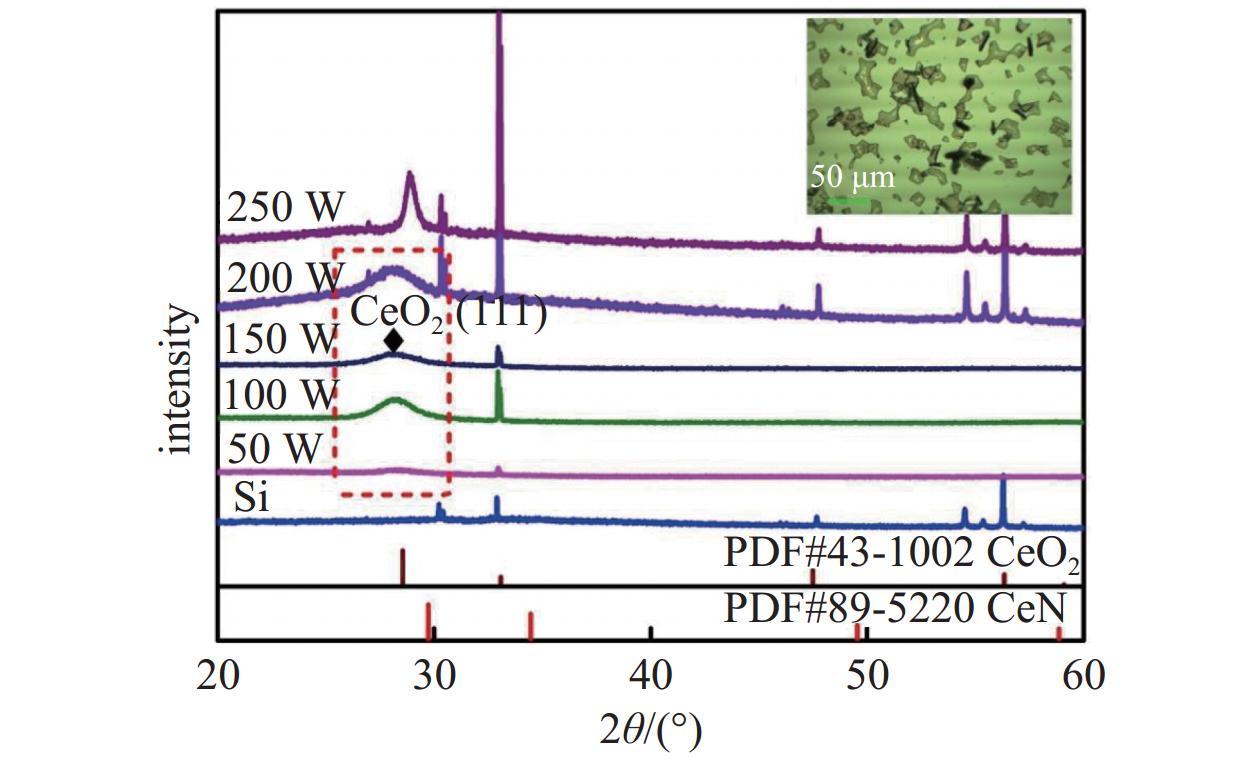
图 2 不同溅射功率条件下制备的CeN薄膜XRD谱图
Figure 2. XRD patterns of CeN films prepared under different sputtering power conditions
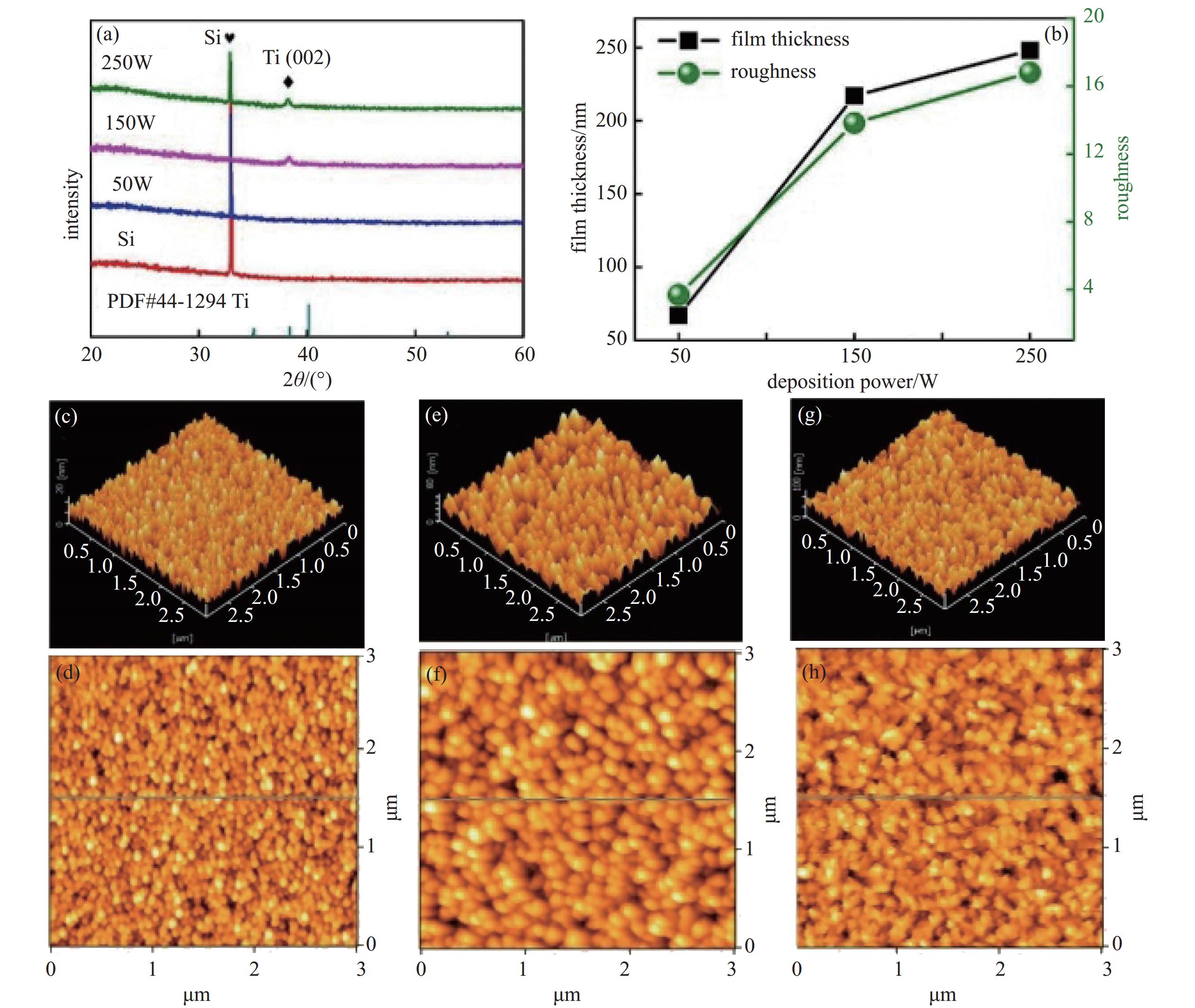
图 3 Ti薄膜XRD和AFM图。(a) 50 W、150 W、250 W功率下制备的Ti薄膜的XRD图谱, (b) 50 W、150 W、250 W功率下制备的Ti薄膜的表面粗糙度和厚度变化曲线。(c)和(d)、(e)和(f)、(g)和(h)分别对应50 W、150 W、250 W功率下制备的Ti薄膜的表面和3D AFM图像
Figure 3. XRD and AFM images of Ti thin films. (a) XRD pattern of Ti thin films prepared at power levels of 50 W, 150 W and 250 W, (b) surface roughness and thickness variation curves of Ti thin films prepared at power levels of 50 W, 150 W and 250 W. (c) (d) , (e) (f) and (g) (h) correspond to the surface and 3D AFM images of Ti thin films prepared at 50 W, 150 W and 250 W power, respectively
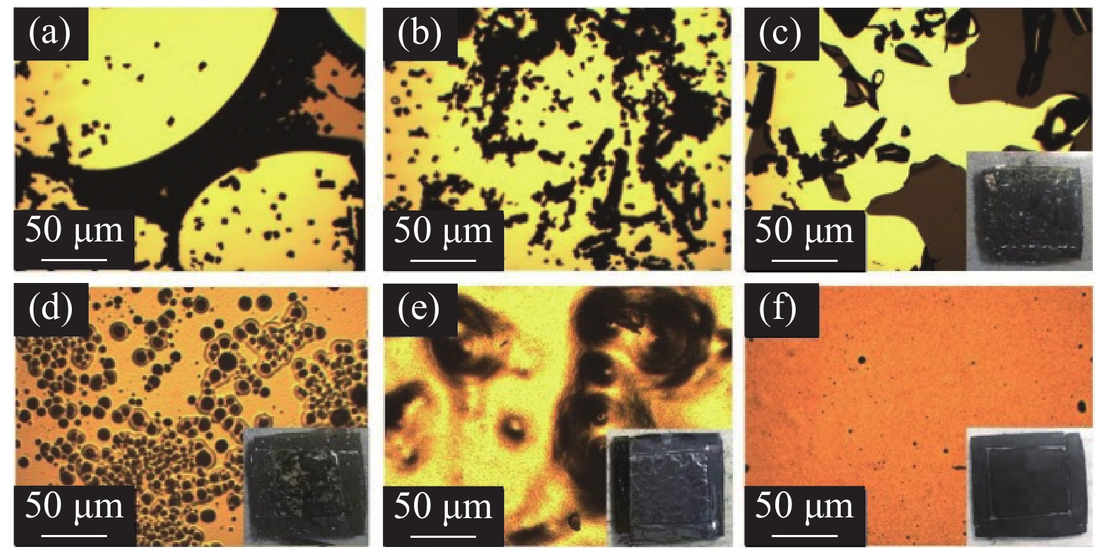
图 4 Ti/CeN复合薄膜的光学显微镜和宏观图像。 (a)、(b)为20 nm Ti/CeN复合薄膜在光学显微镜下1 min内连续拍摄图像;(c)(d)(e)(f)为200 nm Ti/CeN、600 nm Ti/CeN、1.2 μm Ti/CeN和2.4 μm Ti/CeN复合薄膜在大气环境中暴露30 min光学显微镜图像和宏观图像
Figure 4. Optical microscopy and macroscopic images of Ti/CeN composite thin films. (a) and (b) show the images of 20 nm Ti/CeN composite thin film taken under an optical microscope for 1 minute, (c) (d) (e) (f) 200 nm Ti/CeN, 600 nm Ti/CeN, 1.2 μm Ti/CeN and 2.4 μm Optical microscope images and macroscopic images of Ti/CeN composite films exposed to atmospheric environment for 30 minutes
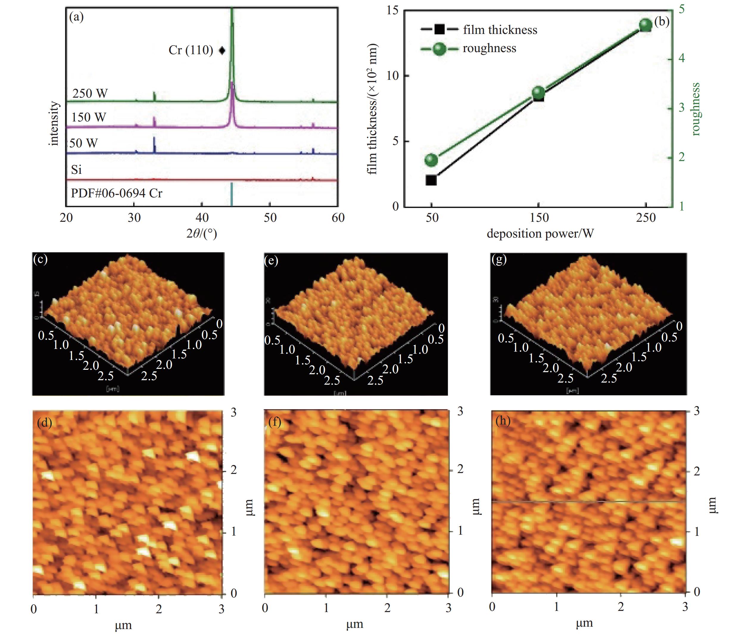
图 5 Cr薄膜XRD和AFM图。(a)为50 W、150 W、250 W功率下制备的Cr薄膜的XRD图谱,(b)为50 W、150 W、250 W功率下制备Cr薄膜表面粗糙度和厚度变化曲线,(c)(d)、(e)(f)、(g)(h)分别是50 W、150 W、250 W功率下制备的Cr薄膜的表面和3D AFM图像
Figure 5. XRD and AFM images of Cr thin films. (a) shows the XRD patterns of Cr films prepared at 50 W, 150 W and 250 W power, (b) the surface roughness and thickness change curves of Cr films were prepared at 50 W, 150 W and 250 W power, (c) (d), (e) (f) and (g) (h) are surface and 3D AFM images of Cr films prepared at 50 W, 150 W and 250 W power, respectively

图 6 Cr/CeN复合薄膜XRD图。 (a)不同厚度制备的Cr/CeN复合薄膜XRD谱图,(b)不同厚度制备的Cr/CeN复合薄膜局部缩放XRD谱图
Figure 6. XRD pattern of Cr/CeN composite thin films. (a) XRD patterns of Cr/CeN composite films prepared with different thicknesses. (b) local scaling XRD patterns of Cr/CeN composite films prepared with different thicknesses
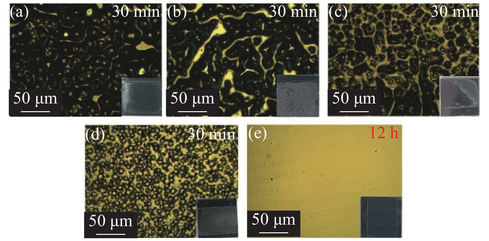
图 7 Cr/CeN复合薄膜的光学显微镜和宏观图像。 (a)、(b)、(c)、(d)分别是20 nm、100 nm、600 nm、1.2 μm Cr/2 μm CeN复合薄膜暴露大气30 min的光学显微镜图像和宏观图像,(e)为2.4 μm Cr/2 μm CeN复合薄膜暴露大气12 h后的光学显微镜图像和宏观图像
Figure 7. Optical microscopy and macroscopic images of Cr/CeN composite thin films (a) , (b) , (c) and (d) are optical microscope images and macro images of 20 nm, 100 nm, 600 nm, 1.2 μm Cr/2 μm CeN composite films exposed to the atmosphere for 30 minutes, respectively, (e) optical microscope images and macroscopic images of 2.4 μm Cr/2 μm CeN composite films exposed to atmosphere for 12 hours
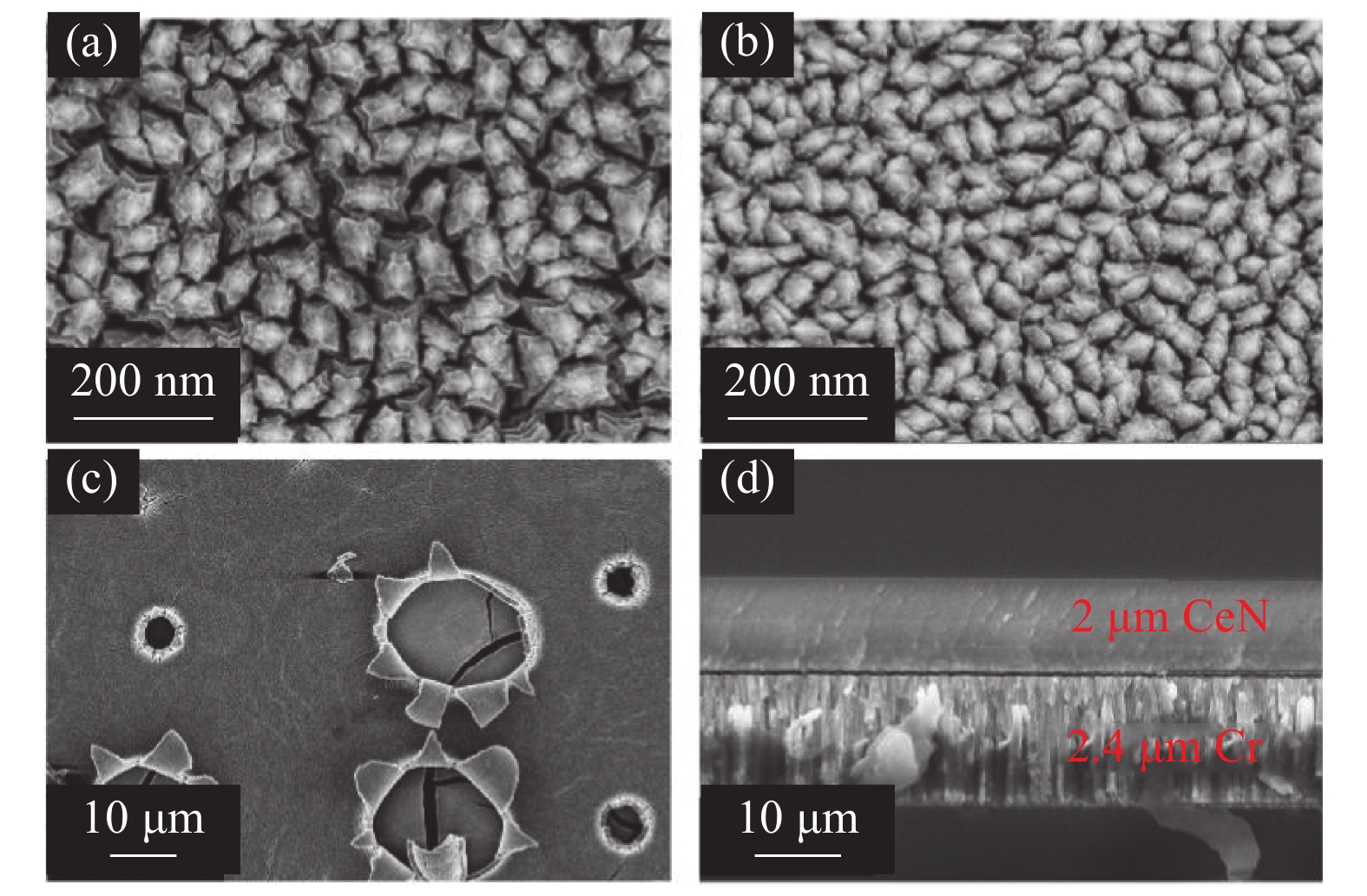
图 8 Cr/CeN复合薄膜SEM图。(a)2.4 μm Cr/2 μm CeN复合薄膜表面形貌,(b)Si基片上沉积Cr表面形貌,(c)、(d)大气环境中暴露12 h后2.4 μm Cr/2 μm CeN表面和截面形貌
Figure 8. SEM image of Cr/CeN composite films. (a) Surface morphology of 2.4 μm Cr/2 μm CeN composite film, (b) the surface morphology of Cr deposited on Si substrate, (c), (d) surface and cross section morphology of 2.4 μm Cr/2 μm CeN after exposure to atmospheric environment for 12 hours

图 9 CeN复合薄膜氧化机理示意图 (a)、(b)、(c)为随着与氧气接触时间增加,薄膜发生的变化
Figure 9. Schematic diagram of oxidation mechanism of CeN composite film (a) (b) and (c) represent the changes that occur in the thin film as the contact time with oxygen increases
表 1 制备参数
Table 1. Preparation parameters
样品 靶材 薄膜厚度/μm 溅射功率/W 氩气流量/(mL/min) 氮气流量/(mL/min) 工作气压/Pa 靶基距/cm CeN Ce 2 200 28 2 0.35 12 Ti Ti 0.02/0.2/0.6/1.2/2.4 150 28 / 0.3 12 Cr Cr 0.02/0.2/0.6/1.2/2.4 150 28 / 0.3 12  下载: 导出CSV
-
[1] Murray R L, Holbert K E. Nuclear energy: an introduction to the concepts, systems, and applications of nuclear processes (7th edition)[M]. Amsterdam: Elsevier, 2015. [2] Hayes S L, Thomas J K, Peddicord K L. Material property correlations for uranium mononitride: I. Physical properties[J]. Journal of Nuclear Materials,1990,171(2-3):262−270 doi: 10.1016/0022-3115(90)90374-V [3] Besmann T M, Ferber M K, Lin H T, et al. Fission product release and survivability of UN-kernel LWR TRISO fuel[J]. Journal of Nuclear Materials,2014,448(1-3):412−419 doi: 10.1016/j.jnucmat.2013.10.034 [4] Suzuki Y, Arai Y. Thermophysical and thermodynamic properties of actinide mononitrides and their solid solutions[J]. Journal of Alloys and Compounds,1998,271-273:577−582 doi: 10.1016/S0925-8388(98)00160-1 [5] Olson W M, Mulford R N R. The decomposition pressure and melting point of uranium mononitride[J]. The Journal of Physical Chemistry,1963,67(4):952−954 doi: 10.1021/j100798a525 [6] Youinou G J, Sen R S. Impact of accident-tolerant fuels and claddings on the overall fuel cycle: a preliminary systems analysis[J]. Nuclear Technology,2014,188(2):123−138 doi: 10.13182/NT14-22 [7] Karoutas Z, Brown J, Atwood A, et al. The maturing of nuclear fuel: past to accident tolerant fuel[J]. Progress in Nuclear Energy,2018,102:68−78 doi: 10.1016/j.pnucene.2017.07.016 [8] Osaka M, Miwa S, Tachi Y. Simple fabrication process for CeO2-MgO composite as surrogate for actinide-containing target for use in nuclear fuel[J]. Ceramics International,2006,32(6):659−663 doi: 10.1016/j.ceramint.2005.04.026 [9] Tennery V J, Botts J L. The chemical characterization of uranium nitrides[J]. Nuclear Technology,1972,13(3):264−272 doi: 10.13182/NT72-A31081 [10] Zhang Y J, Lan J H, Wang C Z, et al. Theoretical investigation on incorporation and diffusion properties of Xe in uranium mononitride[J]. The Journal of Physical Chemistry C,2015,119(11):5783−5789 doi: 10.1021/jp510219a [11] Lawrence Bright E, Rennie S, Siberry A, et al. Comparing the corrosion of uranium nitride and uranium dioxide surfaces with H2O2[J]. Journal of Nuclear Materials,2019,518:202−207 doi: 10.1016/j.jnucmat.2019.03.006 [12] Castano C E, O’Keefe M J, Fahrenholtz W G. Cerium-based oxide coatings[J]. Current Opinion in Solid State and Materials Science,2015,19(2):69−76 doi: 10.1016/j.cossms.2014.11.005 [13] Fahrenholtz W G, O’Keefe M J, Zhou H F, et al. Characterization of cerium-based conversion coatings for corrosion protection of aluminum alloys[J]. Surface and Coatings Technology,2002,155(2-3):208−213 doi: 10.1016/S0257-8972(02)00062-2 [14] Dabalà M, Armelao L, Buchberger A, et al. Cerium-based conversion layers on aluminum alloys[J]. Applied Surface Science,2001,172(3-4):312−322 doi: 10.1016/S0169-4332(00)00873-4 [15] Roleček J, Foral Š, Katovský K, et al. A feasibility study of using CeO2 as a surrogate material during the investigation of UO2 thermal conductivity enhancement[J]. Advances in Applied Ceramics: Structural, Functional and Bioceramics,2017,116(3):123−131 doi: 10.1080/17436753.2016.1264122 [16] Stennett M C, Corkhill C L, Marshall L A, et al. Preparation, characterisation and dissolution of a CeO2 analogue for UO2 nuclear fuel[J]. Journal of Nuclear Materials,2013,432(1-3):182−188 doi: 10.1016/j.jnucmat.2012.07.038 [17] Fronzi M, Soon A, Delley B, et al. Stability and morphology of cerium oxide surfaces in an oxidizing environment: a first-principles investigation[J]. The Journal of Chemical Physics,2009,131(10):104701 doi: 10.1063/1.3191784 [18] Joyce L, Xie Y. A rapid sintering method for cerium nitride pellet: a uranium mononitride surrogate[J]. Ceramics,2022,5(4):1009−1018 doi: 10.3390/ceramics5040072 [19] O'Dell K D, Hensley E B. The decomposition pressure, congruent melting point and electrical resistivity of cerium nitride[J]. Journal of Physics and Chemistry of Solids,1972,33(2):443−449 doi: 10.1016/0022-3697(72)90025-X [20] Schram R P C, Boshoven J G, Cordfunke E H P, et al. Enthalpy increment measurements of cerium mononitride, CeN[J]. Journal of alloys and compounds,1997,252(1-2):20−23 doi: 10.1016/S0925-8388(96)02707-7 [21] Bayoǧlu A S, Lorenzelli R. Oxygen diffusion in fcc fluorite type nonstoichiometric nuclear oxides MO2± x[J]. Solid State Ionics,1984,12:53−66 doi: 10.1016/0167-2738(84)90130-9 [22] Wan Y, Yi T M, Fu Y J, et al. Structure and oxidation properties of CeN thin films prepared by DC reactive magnetron sputtering[J]. Surface and Coatings Technology,2020,381:125168 doi: 10.1016/j.surfcoat.2019.125168 [23] Chen D F, Mei D, Li Y Q, et al. Protective nature of cerium-based oxides coating against Mg corrosion in Hanks’ balanced salt solution[J]. Corrosion Science,2023,219:111255 doi: 10.1016/j.corsci.2023.111255 [24] Boyer R R. An overview on the use of titanium in the aerospace industry[J]. Materials Science and Engineering: A,1996,213(1-2):103−114 doi: 10.1016/0921-5093(96)10233-1 [25] Brunette D M, Tengvall P, Textor M, et al. Titanium in medicine: material science, surface science, engineering, biological responses and medical applications[M]. Berlin: Springer, 2001 [26] Shoesmith D W, Ikeda B M, LeNeveu D M. Modeling the failure of nuclear waste containers[J]. Corrosion,1997,53(10):820−829 doi: 10.5006/1.3290267 [27] Idriss H. Surface reactions of uranium oxide powder, thin films and single crystals[J]. Surface Science Reports,2010,65(3):67−109 doi: 10.1016/j.surfrep.2010.01.001 [28] Chen H, Wang X M, Zhang R Q. Application and development progress of Cr-based surface coatings in nuclear fuel element: I. Selection, preparation, and characteristics of coating materials[J]. Coatings,2020,10(9):808 doi: 10.3390/coatings10090808 [29] Lin C, Song Y, Cao L X, et al. Oxygen reduction catalyzed by Au-TiO2 nanocomposites in alkaline media[J]. ACS Applied Materials & Interfaces,2013,5(24):13305−13311 [30] Lv X W, Tao L M, Cao M L, et al. Enhancing photoelectrochemical water oxidation efficiency via self-catalyzed oxygen evolution: a case study on TiO2[J]. Nano Energy,2017,44:411−418 [31] Wang T, Chen Z, Wang G Q, et al. Microstructure evolution of polycrystalline Ti2AlN MAX phase film during post-deposition annealing[J]. Journal of the European Ceramic Society,2018,38(15):4892−4898 doi: 10.1016/j.jeurceramsoc.2018.07.028 -
计量
- 文章访问数: 763
- HTML全文浏览数: 763
- PDF下载数: 4
- 施引文献: 0