
 首页
首页 登录
登录 注册
注册


-
介质阻挡放电(Dielectric Barrier Discharge, DBD)是实现大气压辉光放电(Atmospheric Pressure Glow Discharge, APGD)的重要方式之一[1],在材料表面改性[2-4]、薄膜沉积、等离子体医学等方面有广泛应用前景[5]。介质阻挡放电通过介质层表面电荷积累产生的反向电场抑制电弧的产生,实现大气压下较大功率下的稳定放电。DBD的电子密度通常仅约为1010 cm−3,大大限制了其使用[6]。为了解决这个问题,Kunhardt[7-8]提出了一种毛细管等离子体电极放电(Capillary Plasma Electrode Discharge, CPED),这种放电引入带有许多微小孔的电介质层,提高了等离子体性能。图1所示给出了CPED的结构示意图。CPED通过带有许多毛细管的介质层来改变空间电场强度分布,产生等离子体射流,提高等离子体的的性能。电子密度提高至1012 cm−3,拓宽了等离子体的应用范围。Lukasz Moskwinski在他的学位论文中研究了大气压下的CPED,将CPED分为三种放电模式:汤生放电模式、均匀放电模式和射流模式[9]。K. H.Becker等[10]在硅或陶瓷中制造小尺寸的CPED器件,这些阵列具有许多良好的光学和电学特性,非常适合于医疗诊断、显示和环境传感应用,讨论和研究了微等离子体器件的几种结构及其基本性质和应用。A.Koutsospyros等[11]将CPED等离子体用于碳氢化合物分解,研究了反应器体积、物种停留时间等对分解过程的影响,电子密度达到1012 cm−3,平均电子能量约为5−6 eV。
多孔阳极氧化铝是一种非常优异的介质,通过阳极氧化方式在铝表面制备规则纳米级多孔状多晶结构的多孔阳极氧化铝层应用广泛[12- 13]。多孔阳极氧化铝可用作介质阻挡放电的介质层。S J Park等[14- 15]研究了表面具有多孔阳极氧化铝的圆柱形电极间的共面介质阻挡放电,在50 Torr氖气和空气中实现辉光放电。S Hussain 等[16-19]研究了大气压下射频DBD的放电特性,放电装置中的介质层为0.3 mol/L草酸溶液、恒压40 V下制备的多孔阳极氧化铝,采用电流-电压特性和毫秒图像来识别放电模式。Il Gyo Koo等[20]研究了大气压高温条件下的介质阻挡放电的放电性质,放电中采用多孔陶瓷层作为放电介质,使用H2O/SO2混合物生产氢气。Toshiyuki Kawasaki等[21]制备了多孔阳极氧化铝,用于介质阻挡放电中介质层。
数值模拟是一种了解大气压放电过程的好方法。Jovanovic A P 和Abidat R等进行了介质阻挡放电过程的模拟研究工作,他们基于Comsol Multiphysics模拟软件,研究了介质阻挡放电过程[22- 23]。
应用多孔阳极化铝进行介质阻挡放电的研究已经开展多年,但从毛细管等离子体电极放电的角度研究多孔阳极氧化铝介质层对放电的影响还很少见。本研究组在前期工作中已经开展多孔阳极氧化铝为介质层的介质阻挡放电的关实验研究工作[5],本文将在此基础上,应用Comsol Multiphyiscs 6.0模拟放电过程,对比分析大气压下基于多孔阳极氧化铝的毛细管等离子体电极放电和介质阻挡放电的放电过程,探讨多孔阳极氧化铝介质对放电过程的影响。
-
实验中采用自行设计组装的阳极氧化设备[5]。采用商用铝板(50 mm×100 mm×1 mm)为基板,经清洗、去除表面氧化层等工序后,与一块石墨板(50 mm×100 mm×3 mm)构成相对电极,一同浸入草酸溶液(0.3 mol/L,溶液温度为15℃)中。铝板和石墨板分别连接在直流电源的正极、负极,电源设置为恒压模式(电压设为40 V)。
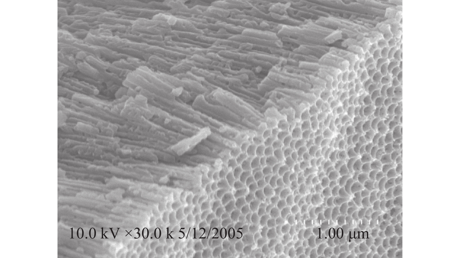
图2给出了多孔阳极氧化铝的扫描电子显微镜图片,由图中可以看出:多孔氧化铝由分布均匀、纳米级、形状规则的多孔状结构构成。
在放电中,应用高压高频正弦交流电源(频率为10 kHz)进行大气压空气放电测试。放电装置采用具有双介质层的体放电结构(如图1所示)。介质层分别为石英(0.20 mm)+石英(0.20 mm)、石英(0.20 mm)+多孔阳极氧化铝(9.7 μm),其中上层介质层为ITO玻璃。气体间隙为1.1 mm。应用照相机记录放电过程。
图3给出了两种放电过程对比,两种放电的介质层分别采用石英+石英和石英+多孔阳极氧化铝。由图中可以看出:基于多孔阳极氧化铝的介质阻挡放电具有更好的均匀性,放电稳定性较好。介质层材料的性能对放电稳定性有很大的影响;基于多孔阳极氧化铝的毛细管等离子体电极放电,具有优于应用石英板的放电性能,放电更稳定。
-
为了对比大气压下基于多孔阳极氧化铝的毛细管等离子体电极放电和介质阻挡放电,应用COMSOL Multiphysics 6.0软件,建立介质阻挡放电模型和同几何参数、同介质材料的毛细管等离子体电极放电的模型。图4给出了介质阻挡放电模拟的模型与网格图。模型采用石英和陶瓷作为介质层,石英和陶瓷的介电常数分别取为3.75和9.10。石英层和陶瓷层厚度分别为0.2 mm和0.02 mm,根据等离子体物理特点建立网格。
图5给出了基于多孔阳极氧化铝的毛细管等离子体电极放电模拟的模型与网格图。放电模型采用石英和多孔阳极氧化铝作为介质层,石英和多孔阳极氧化铝的介电常数分别取为3.75和9.10,放电结构几何参数和介质的介电常数与介质阻挡放电相同。多孔阳极氧化铝孔直径、膜底厚度和宽径比分别为:0.02 mm、0.02 mm和1.5。模拟中采用氩气作为放电气体。模拟中使用正弦交流电源,电压公式如式(1)所示。
电源的频率和电压峰值为10 kHz和600 V。
-
为了比较分析大气压下DBD与基于PAA的CPED的放电特性,实验结果中比较分析了两种放电的电子密度、电子温度及其空间分布。
图6给出了毛细管等离子体电极放电和介质阻挡放电模拟中的电子密度分布图,时间选为电子密度取最大值时刻。从图中可以看出:在介质阻挡放电中,电子密度的最大值和最小值分别为3.99×10¹¹ m−3和5.92×10⁵ m−3;在毛细管等离子体电极放电中,电子密度的最大值和最小值分别为1.40×10¹⁴ m−3和7.91×10⁶ m−3。
图7给出了毛细管等离子体电极放电和介质阻挡放电模拟中的电子温度分布图。选取电子温度取最大值时刻进行绘图。从图中可以看出:在介质阻挡放电中,电子温度的最大值和最小值分别为3.85 eV和0.94 eV;在毛细管等离子体电极放电中,电子温度最大值和最小值分别为4.18 eV和1.2 eV。
由图6和7,相比于介质阻挡放电,应用多孔阳极氧化铝的毛细管等离子体电极放电等离子体具有更高的电子密度和电子温度:电子密度从3.99×10¹¹ m−3提高到1.40×10¹⁴ m−3,电子温度从3.65 eV提高到4.18 eV。电子密度提高约两个数量级,电子温度提高约20%。
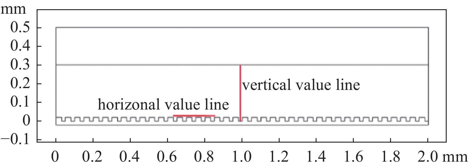
为了进一步研究放电过程中多孔阳极氧化铝对介质阻挡放电的影响,在放电区域选择水平取值线和垂直取值线,取值线如图8所示。水平取值线选择在多孔阳极氧化铝上方约0.001 mm处(覆盖五个孔),垂直取值线长0.3 mm,贯穿放电空间。
图9给出了垂直方向上毛细管等离子体电极放电和介质阻挡放电模拟中的电子密度分布图,取值线如图8所示。从图中可以看出:在介质阻挡放电和毛细管等离子体电极放电中,等离子体中的电子主要分布在介质层附近区域;介质阻挡放电中,电子密度仅为3.99×10¹¹ m−3,毛细管等离子体电极放电中的电子密度的最大值可达1.40×10¹⁴ m−3;介质阻挡放电中的电子密度梯度变化平滑,毛细管介质阻挡放电中毛细管区域出现电子密度区域变化。
图10给出了垂直取值线上毛细管等离子体电极放电和介质阻挡放电中的电子温度分布图,取值线如图8所示。在介质阻挡放电中的电子温度分布均匀平滑,而毛细管等离子体电极放电中电子温度出现一些波动;毛细管等离子体电极放电中的电子温度高于介质阻挡放电。
图11给出了水平取值线上毛细管等离子体电极放电和介质阻挡放电中的电子密度分布。在介质阻挡放电中,电子密度在水平方向上分布均匀;毛细管等离子体电极放电中的电子密度分布随着孔的位置而出现明显的波动,孔正上方电子密度出现尖锐的峰值分布。
图12给出了水平取值线上毛细管等离子体电极放电和介质阻挡放电模拟中的电子温度分布。在介质阻挡放电中电子温度分布均匀;毛细管等离子体电极放电中,电子温度出现波动,孔间介质层区域,电子温度出现峰值。
基于多孔阳极氧化铝的毛细管等离子体电极放电的放电性能明显优于同结构的介质阻挡放电。在基于多孔阳极氧化铝的等离子体电极放电中,最大电子密度和电子温度都明显高于同结构的介质阻挡放电,最大电子密度高约2个数量级,电子温度高约20%。多孔阳极氧化铝介质结构上的多孔结构,给放电带来了介质层厚度的变化,由此导致空间的电场强度分布出现波动,电子温度和电子密度出现相应波动;多孔结构增加了介质层的表面积,表面积累的电荷增大,表面积累电荷产生额外的电场强度,与电源电压的电场强度相叠加,共同影响空间的放电过程和等离子体性质。
-
本文通过实验和模拟方式,对比分析了基于多孔阳极氧化铝的毛细管等离子体电极放电和介质阻挡放电的放电过程。应用阳极氧化方法在铝表面制备的多孔阳极氧化铝(Porous anodic alumina, PAA)作为介质层研究了毛细管等离子体电极放电。应用模拟软件模拟分析了相同几何参量的介质阻挡放电和毛细管等离子体电极的放电过程。结果表明:应用多孔阳极氧化铝为介质的毛细管等离子体放电过程更稳定,放电中产生的更密的微放电有助于降低放电击穿电压和提高放电稳定性;多孔阳极氧化铝介质层的毛细管等离子体电极放电具有更高的电子密度和电子温度,电子密度高出两个数量级,电子温度高20%;等离子体参数具有随孔分布的周期性;放电中产生的等离子体射流模式,提高了放电稳定性。本研究结果对于大气压下等离子体电极放电及其相关应用具有一定的参考意义。
基于多孔阳极氧化铝的大气压毛细管等离子体电极放电研究
Atmospheric Capillary Plasma Electrode Discharge Based on Porous Anodic Alumina
-
摘要: 通过实验和模拟方式,对比分析了介质阻挡放电和基于多孔阳极氧化铝的毛细管等离子体电极放电。应用阳极氧化法制备的多孔阳极氧化铝(Porous anodic alumina, PAA)作为介质层进行了毛细管等离子体电极放电。研究了多孔阳极氧化铝介质层对毛细管等离子体电极放电的影响,对比分析了相同几何参量的介质阻挡放电和毛细管等离子体电极放电的放电过程。结果表明:应用多孔阳极氧化铝介质的毛细管等离子体电极放电更稳定,放电中产生的更密的微放电有助于提高放电的稳定性;多孔阳极氧化铝介质层的毛细管等离子体电极放电具有相对于介质阻挡放电高出两个数量级的电子密度和更高的电子温度。等离子体参数具有与多孔阳极氧化铝的孔分布同步的周期性,产生了等离子体射流模式,提高了放电稳定性。
-
关键词:
- 多孔阳极氧化铝 /
- 毛细管等离子体电极放电 /
- 介质阻挡放电 /
- 放电稳定性
Abstract: Dielectric barrier discharge and capillary plasma electrode discharge based on porous anodic alumina were compared and analyzed through experiments and simulations. A layer of porous anodic alumina (PAA) was prepared on the surface of aluminum plates using the anodizing method. The effect of the porous anodic alumina dielectric layer on capillary plasma electrode discharge was studied. The processes of dielectric barrier discharge and capillary plasma electrode discharge with the same geometric parameters were compared and analyzed. It is shown that the capillary plasma electrode discharge with porous anodic alumina is more stable. Dense micro discharge paths generated in the discharge are helpful to improve the stability. The capillary plasma electrode discharge of porous anodic alumina has two orders of magnitude higher electron density and higher electron temperature than the dielectric barrier discharge. Plasma parameters have a periodicity with the distribution of pores on the porous anodic alumina, which results in the plasma jet mode and improves the discharge stability. -

-
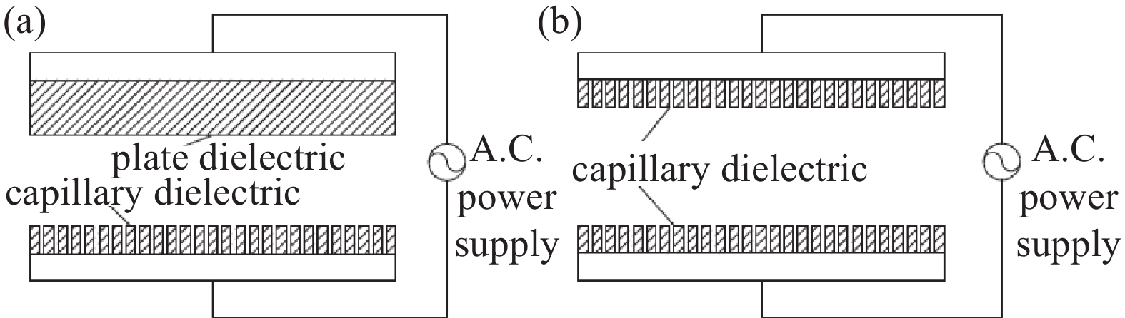
图 1 毛细管等离子体电极放电装置示意图。(a)单毛细管介质层,(b)双毛细管介质层
Figure 1. Schematic diagram of capillary-plasma-electrode configuration. (a) Single capillary dielectric layer, (b) double capillary dielectric layer
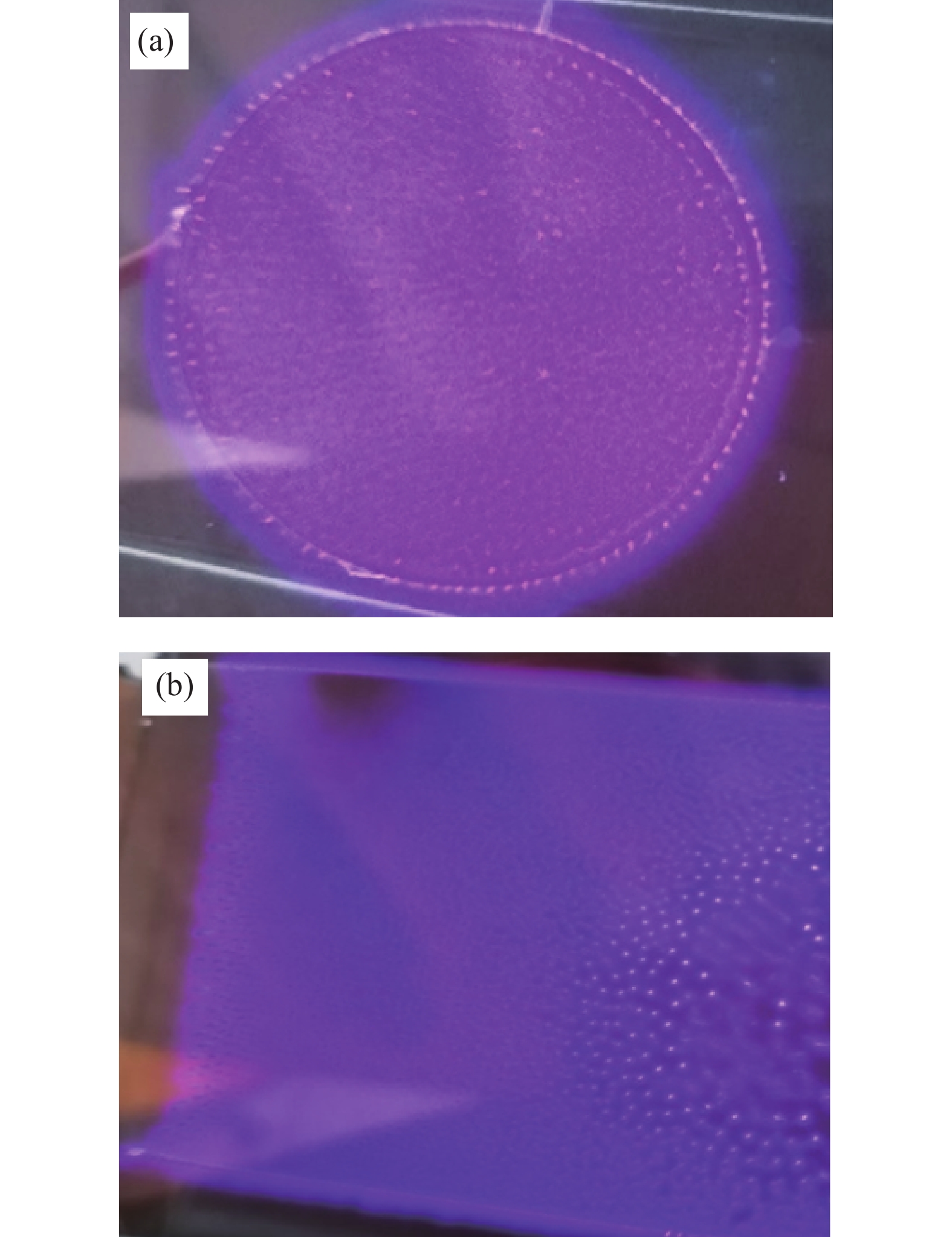
图 3 放电过程图像对比。(a)介质阻挡放电(0.20 mm Quartz+0.20 mm Quartz),(b)毛细管等离子体电极放电(0.20mm Quartz + 9.7 μm PAA)
Figure 3. Comparison of discharge images. (a) DBD (0.20 mm Quartz+0.20 mm Quartz), (b) CPED (0.20 mm Quartz + 9.7 μm PAA)
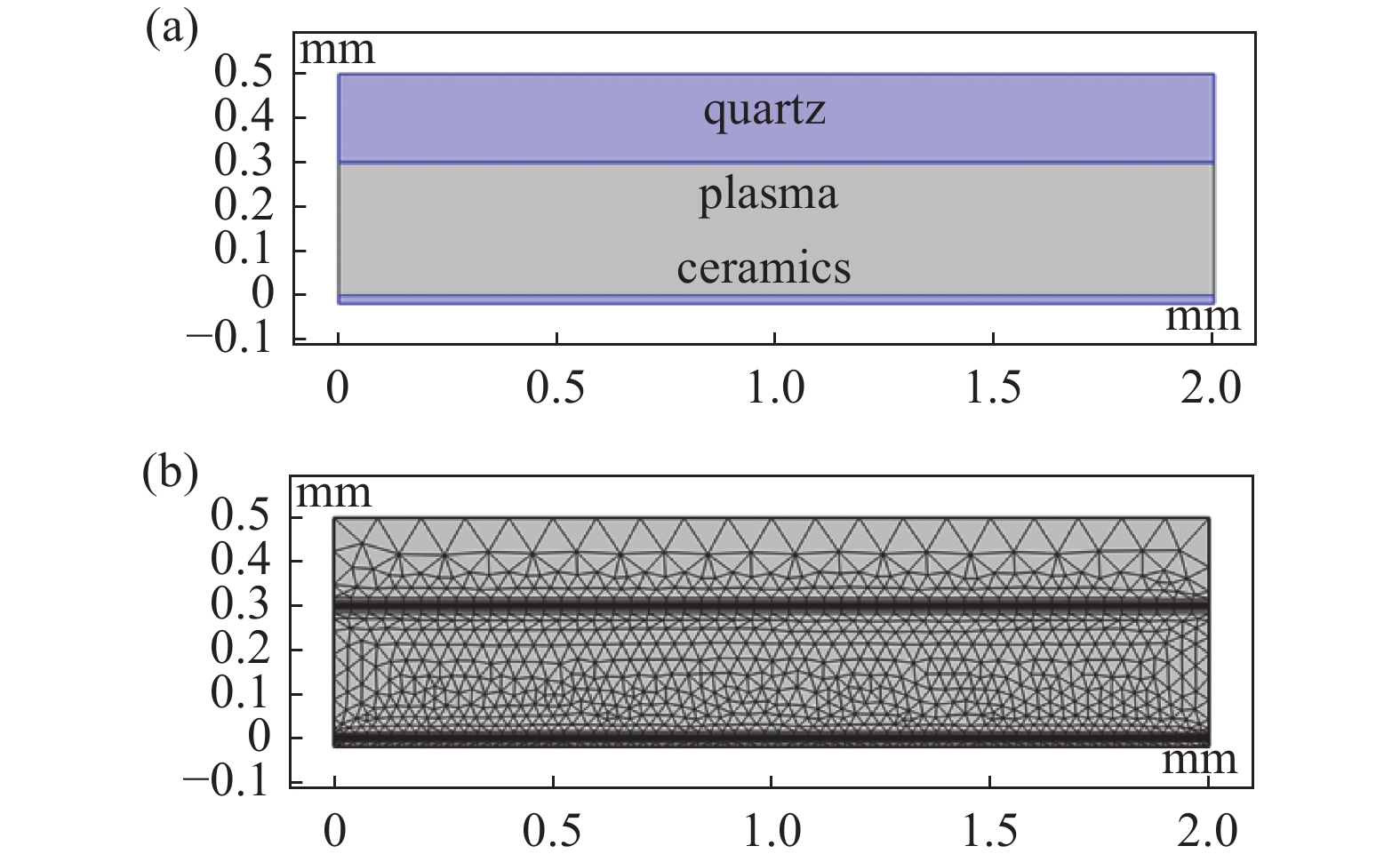
图 4 介质阻挡放电模拟示意图。 (a)模型,(b)网格图
Figure 4. Schematic images of dielectric barrier discharges. (a) Model, (b) grid picture
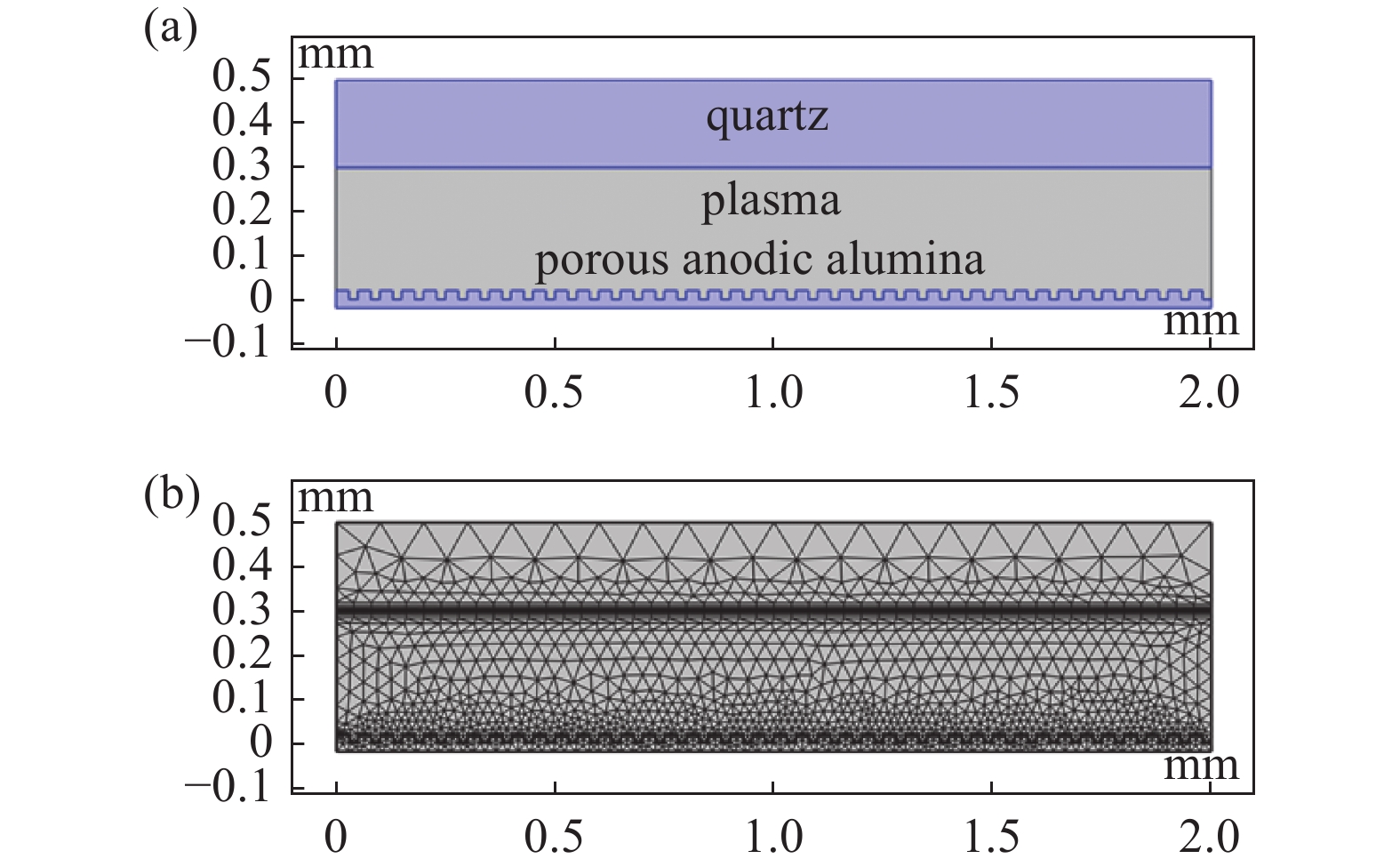
图 5 基于多孔阳极氧化铝的CPED模拟示意图。(a)模型,(b)网格图
Figure 5. Schematic images of capillary plasma electrode discharge. (a) Model, (b) grid picture
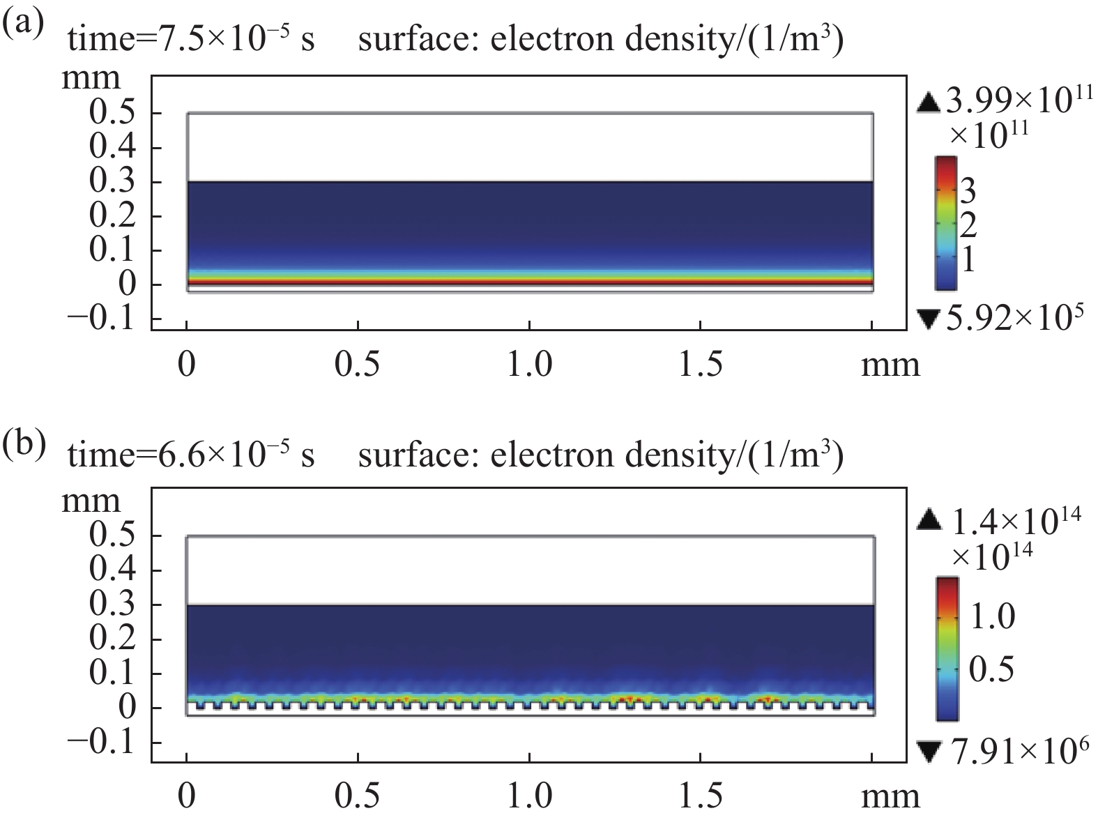
图 6 空间电子密度分布比较。(a) DBD, (b) CPED
Figure 6. Comparison of electron density. (a) DBD, (b) CPED
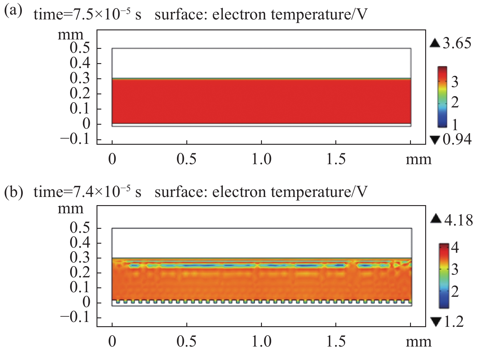
图 7 空间电子温度分布比较。(a) DBD,(b) CPED
Figure 7. Comparison of electron temperature. (a) DBD, (b) CPED
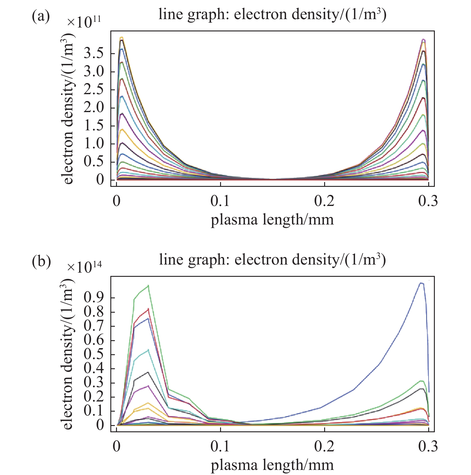
图 9 垂直方向电子密度分布比较。(a) DBD, (b) CPED
Figure 9. Electron density on the vertical value line. (a) DBD, (b) CPED
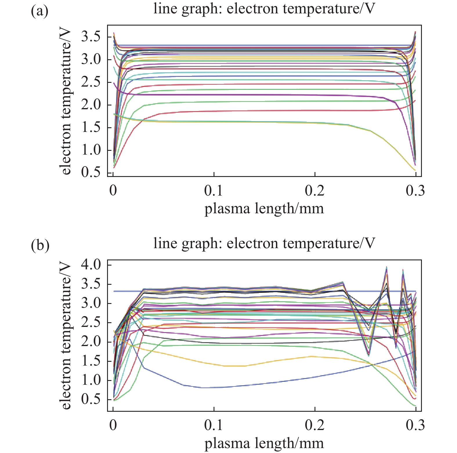
图 10 垂直方向电子温度分布比较。(a) DBD,(b) CPED
Figure 10. Electron temperature on the vertical value line. (a) DBD, (b) CPED
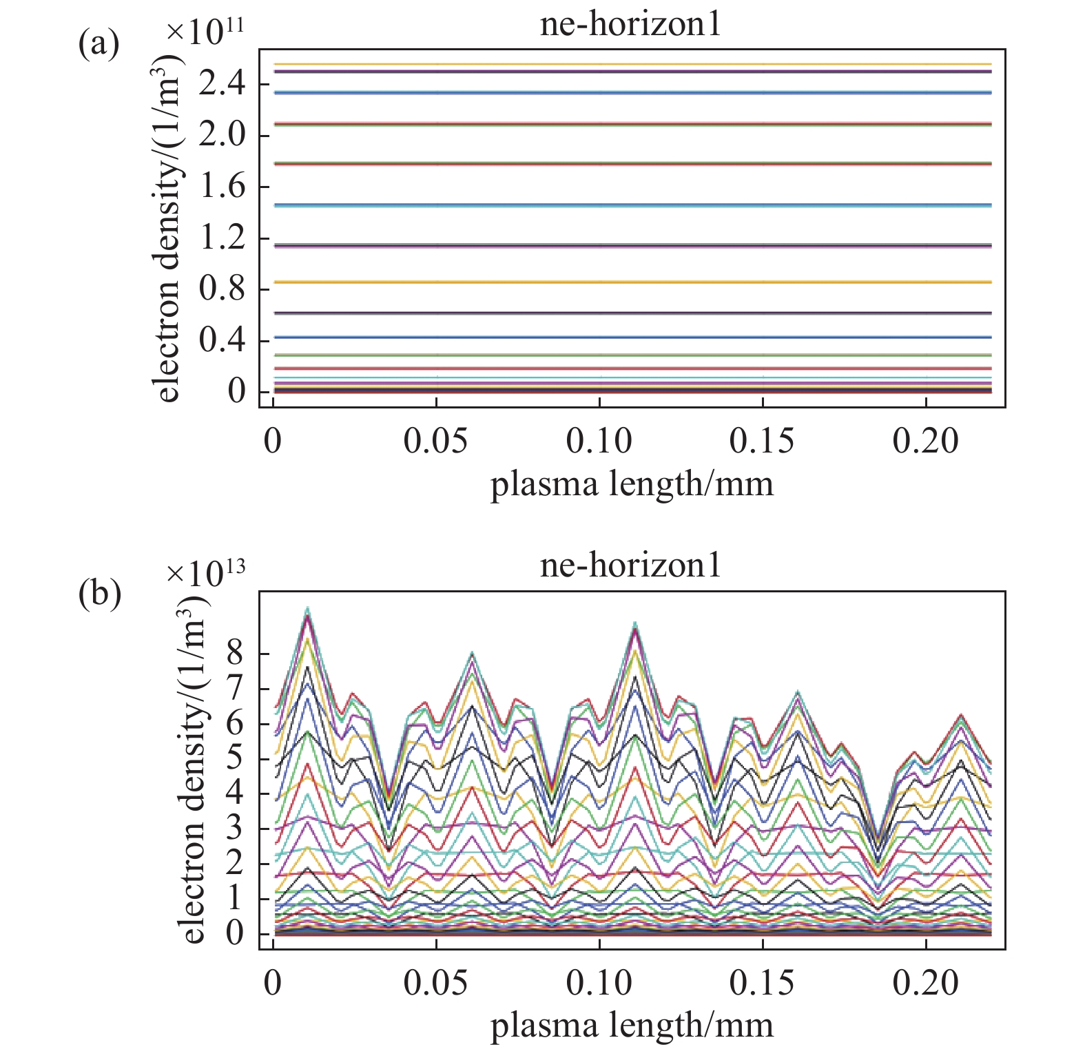
图 11 水平方向电子密度分布比较。(a) DBD,(b) CPED
Figure 11. Electron density on the horizontal value line. (a) DBD, (b) CPED
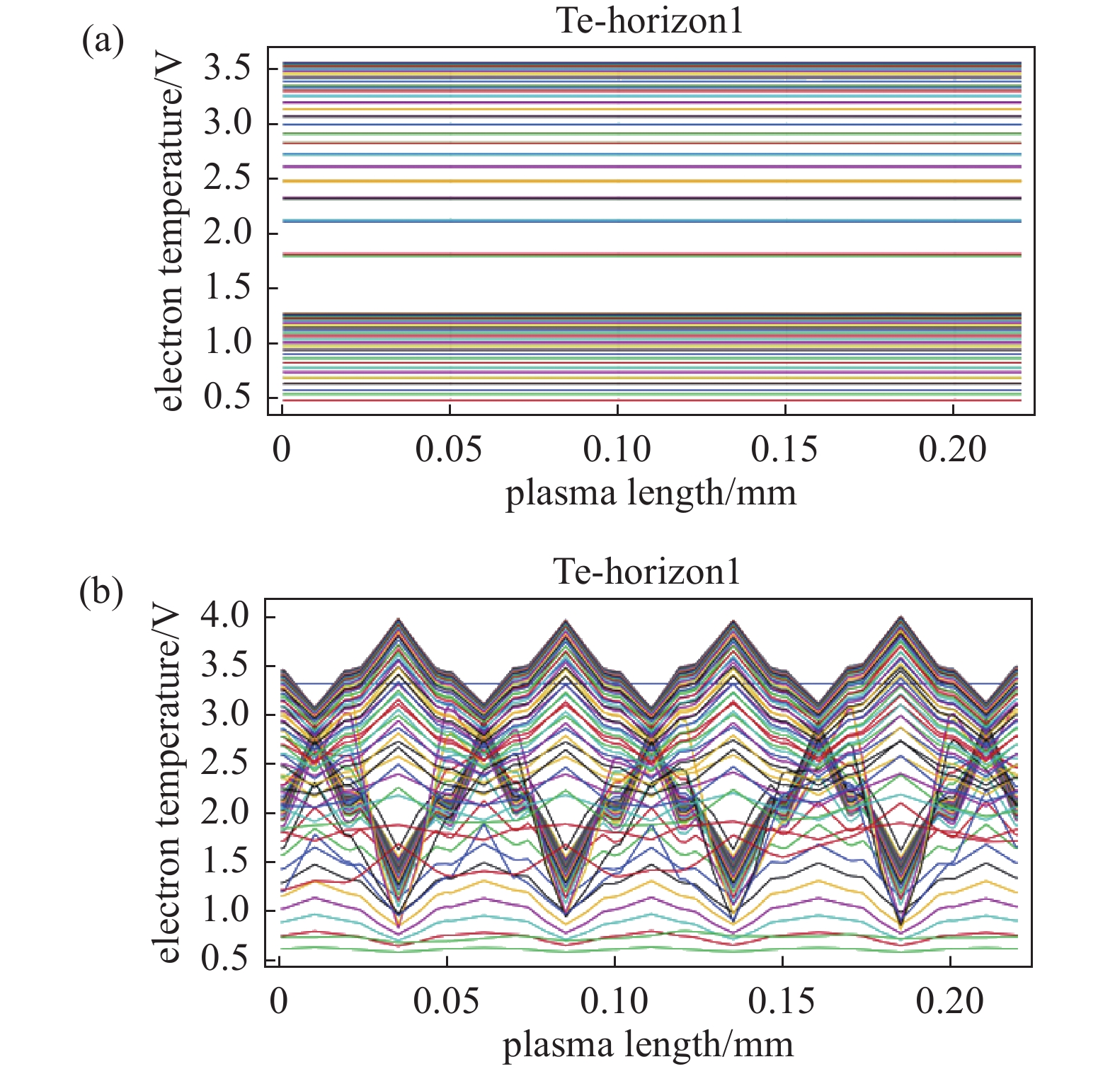
图 12 水平方向电子温度分布比较。(a) DBD,(b) CPED
Figure 12. Electron temperiature on the horizontal value line. (a) DBD, (b) CPED
表 1 基于多孔阳极氧化铝的毛细管等离子体电极放电模拟的主要参数
Table 1. Parameters of capillary plasma electrode discharge simulation based on porous anodic alumina
Name Value Description f0 10 kHz RF Frequency Vrf 600 V Applied voltage dplate 0.1 m Plate diameter Th 0.001 m Thickness Ta 2.0×10⁻⁵ m PAA bottom thickness d2 3×10⁻⁴ m Distance of Gap d1 2×10⁻⁴ m Distance of Quartz Dp 0.8~2.2×10⁻⁵ m Diameter of Pore r 1.0~4.5 ratio of Depth to Dp rx 2.0~5.5 2.0-5.5 NPAA 40 Number of PAA  下载: 导出CSV
表 2 大气压放电模拟的主要反应过程
Table 2. Main reactions in atmospheric pressure discharge simulation
No. Reactons 1 e+Ar=>e+Ar 2 e+Ar=>e+Arm 3 e+Arm=>e+Ar 4 e+Ar=>2e+Ar+ 5 e+Arm=>2e+Ar+ 6 Arm+Arm=>e+Ar+Ar+ 7 Arm+Ar=>Ar+Ar
下载: 导出CSV
-
[1] Fridman A,Chirokov A,Gutsol A. Non-thermal atmospheric pressure discharges[J]. Journal of Physics D:Applied Physics,2005,38(2):R1−R24 doi: 10.1088/0022-3727/38/2/R01 [2] Wang K,Li J,Ren C S,et al. Surface modification of polyethylene (PE) films using dielectric barrier discharge plasma at atmospheric pressure[J]. Plasma Science and Technology,2008,10(4):433−437 doi: 10.1088/1009-0630/10/4/07 [3] Wang K,Li J. Surface modification of polyethylene membrane with air dielectric barrier discharge plasma[J]. Chinese Journal of Vacuum Science and Technology,2013,33(4):337−341 (王坤,李建. 空气介质阻挡放电对聚乙烯表面吸湿性的改性研究[J]. 真空科学与技术学报,2013,33(4):337−341(in chinese) Wang K, Li J. Surface modification of polyethylene membrane with air dielectric barrier discharge plasma[J]. Chinese Journal of Vacuum Science and Technology, 2013, 33(4): 337-341 (in chinese) [4] Zhuang Y,Liu F,Chu H J,et al. Comparison study of PP hydrophilic surface modification by Ar/H2O dielectric barrier discharge excited by AC and nanosecond pulse voltage[J]. High Power Laser and Particle Beams,2021,33(6):065017-1−9 (庄越,刘锋,储海靖,等. 交流和纳秒脉冲Ar/H2O介质阻挡放电聚丙烯材料表面亲水性改性对比研究[J]. 强激光与粒子束,2021,33(6):065017-1−9(in chinese) Zhuang Y, Liu F, Chu H J, et al. Comparison study of PP hydrophilic surface modification by Ar/H2O dielectric barrier discharge excited by AC and nanosecond pulse voltage[J]. High Power Laser and Particle Beams, 2021, 33(6): 065017-1-9 [5] Wang K,Wang S Q,Li J,et al. Influence of porous anodic alumina dielectric on atmospheric pressure dielectric barrier discharge plasma[J]. Chinese Journal of Vacuum Science and Technology,2023,43(2):90−95 (王坤,王世庆,李建,等. 多孔阳极氧化铝介质对大气压介质阻挡放电等离子体的影响[J]. 真空科学与技术学报,2023,43(2):90−95(in chinese) doi: 10.13922/j.cnki.cjvst.202203005 Wang K, Wang S Q, Li J, et al. Influence of porous anodic alumina dielectric on atmospheric pressure dielectric barrier discharge plasma[J]. Chinese Journal of Vacuum Science and Technology, 2023, 43(2): 90-95 (in chinese) doi: 10.13922/j.cnki.cjvst.202203005 [6] Kogelschatz U. Dielectric-barrier discharges: their history, discharge physics, and industrial applications[J]. Plasma Chemistry and Plasma Processing,2003,23(1):1−46 doi: 10.1023/A:1022470901385 [7] Kunhardt E E. Generation of large-volume, atmospheric-pressure, nonequilibrium plasmas[J]. IEEE Transactions on Plasma Science,2000,28(1):189−200 doi: 10.1109/27.842901 [8] Kunhardt E E, Becker K H. Method for generating and maintaining a glow plasma discharge: US6005349[P]. 1999 [9] Moskwinski L. Study of atmospheric pressure Capillary Plasma Electrode Discharge (CPED)[D]. Hoboken: Stevens Institute of Technology, 2009 [10] Becker K H,Schoenbach K H,Eden J G. Microplasmas and applications[J]. Journal of Physics D:Applied Physics,2006,39(3):R55−R70 doi: 10.1088/0022-3727/39/3/R01 [11] Koutsospyros A,Yin S M,Christodoulatos C,et al. Destruction of hydrocarbons in non-thermal, ambient-pressure, capillary discharge plasmas[J]. International Journal of Mass Spectrometry,2004,233(1-3):305−315 doi: 10.1016/j.ijms.2003.12.033 [12] Jessensky O,Müller F,Gösele U. Self-organized formation of hexagonal pore arrays in anodic alumina[J]. Applied physics Letters,1998,72(10):1173−1175 doi: 10.1063/1.121004 [13] Li F Y,Zhang L,Metzger R M. On the growth of highly ordered pores in anodized aluminum oxide[J]. Chemistry of Materials,1998,10(9):2470−2480 doi: 10.1021/cm980163a [14] Park S J,Eden J G. Microdischarge devices with a nanoporous Al2O3 dielectric: operation in Ne and air[J]. IEEE Transactions on Plasma Science,2005,33(2):572−573 doi: 10.1109/TPS.2005.845268 [15] Park S J,Kim K S,Eden J G. Nanoporous alumina as a dielectric for microcavity plasma devices: multilayer Al/Al2O3 structures[J]. Applied Physics Letters,2005,86(22):221501 doi: 10.1063/1.1923747 [16] Hussain S,Qazi H I A,Badar M A. Characteristics of radio-frequency atmospheric pressure dielectric-barrier discharge with dielectric electrodes[J]. Physics of Plasma,2014,21(3):030702 doi: 10.1063/1.4868424 [17] Hussain S,Qazi H I A,Malik A A,et al. Glow modes in radio frequency atmospheric discharge operating with and without anodized electrodes[J]. IEEE Transactions on Plasma Science,2014,42(10):2410−2411 doi: 10.1109/TPS.2014.2326683 [18] Qazi H I A,Sharif M,Hussain S,et al. Spectroscopic study of a radio-frequency atmospheric pressure dielectric barrier discharge with anodic alumina as the dielectric[J]. Plasma Science and Technology,2013,15(9):900−903 doi: 10.1088/1009-0630/15/9/13 [19] Ashraf H,Shah S Z A,Qazi H I A,et al. Electrical features of radio-frequency atmospheric pressure helium discharge with and without dielectric electrodes[J]. Plasma Science and Technology,2019,21(2):025403 doi: 10.1088/2058-6272/aaede1 [20] Koo I G,Choi M Y,Kim J H,et al. Microdischarge in porous ceramics with atmospheric pressure high temperature H2O/SO2 gas mixture and its application for hydrogen production[J]. Japanese Journal of Applied Physics,2008,47(6):4705−4709 doi: 10.1143/JJAP.47.4705 [21] Kawasaki T. Manufacturing of anodic porous alumina for barriers in a dielectric barrier discharge reactor[J]. Journal of Electrostatics,2008,66(7-8):395−400 doi: 10.1016/j.elstat.2008.04.006 [22] Abidat R, Rebiai S, Benterrouche L. Numerical simulation of atmospheric dielectric barrier discharge in helium gas using COMSOL multiphysics[C]//Proceedings of the 3rd International Conference on Systems and Control, Algiers: IEEE, 2013: 29-31 [23] Jovanović A P,Stankov M N,Loffhagen D,et al. Automated fluid model generation and numerical analysis of dielectric barrier discharges using comsol[J]. IEEE Transactions on Plasma Science,2021,49(11):3710−3718 doi: 10.1109/TPS.2021.3120507 -
计量
- 文章访问数: 312
- HTML全文浏览数: 312
- PDF下载数: 3
- 施引文献: 0